
Instruction Manual


Instruction Manual
D102178X012
V260 Valve
September 2012
2
Table 1. Specifications
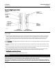
Valve Body Size and End Connection Styles
(1)
NPS 8, 10, 12, 16, 20, and 24 flanged valves with
CL150, CL300, and CL600 raised-face or ring-type
joint flanges compatible with ASME B16.5. See table 2
for face-to-face dimensions. Consult factory for other
pressure ratings.
Maximum Inlet Pressures and Temperatures
(1)
Consistent with CL150, CL300, and CL600
pressure-temperature ratings per ASME B16.34
Maximum Allowable Shutoff Pressure Drop
(1)
For Single-Seal and Dual-Seal Construction:
(Except where further limited by the
pressure-temperature rating of valve body material)
For LF2 valve body material:
CL150: 19.6 bar (285 psi) at 38_C (100_F)
CL300: 51 bar (740 psi) at 38_C(100_F)
CL600: 103 bar (1480 psi) at 38_C(100_F)
Seal Material and Temperature Capability
(1)
J POM (polyoxymethylene) (Standard) -29 to 82_C
(-20 to 180_F)
J PTFE/PEEK
(2)(3)
(Optional) -29 to 93_C(-20to
200_F)
Flow Characteristic
Modified equal percentage
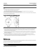
Flow and Shutoff Direction
Unidirectional flow for Fisher V260 is forward flow.
Seal is upstream.
J Single Seal Constructions: Should be used for
unidirectional flow and unidirectional shutoff only.
J Dual Seal Constructions: V260A and V260C may be
used for unidirectional or bidirectional flow. V260B
should be used for unidirectional flow only for most
effective anti-cavitation protection. Bidirectional
shutoff requires the dual seal construction.
Shutoff Classification
Single-Seal Composition Constructions: 0.001% of
maximum valve capacity (less than 10% of ANSI/FCI
70-2 Class IV and IEC 60534-4)
Dual-Seal Composition Constructions: 0.001% of
maximum valve capacity (less than 10% of ANSI/FCI
70-2 Class IV and IEC 60534-4)
Maximum Ball Rotation
90 degrees
Actuator Mounting
Right-hand or left-hand mounted as viewed from the
valve inlet for forward flow
Approximate Weight
See table 2
1. The pressure-temperature limits in this instruction manual and any applicable standard or code limitation for valve should not be exceeded.
2. PTFE stands for Polytetrafluorethylene, and PEEK stands for Polyetheretherketone.
3. Temperature limits of PTFE/PEEK is limited due to standard nitrile O-ring. Contact your Emerson Process Management sales office for higher temperature options, up to 232_C(450_F).
Installation
WARNING
D To avoid personal injury, always wear protective gloves, clothing, and eyewear when performing any installation
operations.
D To avoid personal injury or property damage resulting from the bursting of pressure retaining parts, be certain the
service conditions do not exceed the limits given in this manual.
D To avoid personal injury or property damage that can result from the sudden release of process pressure if valve or
mating pipe flange pressure ratings are exceeded, provide a relief valve for over-pressure protection as required by
government or accepted industry codes and good engineering practices.
D Service conditions are limited for valve and trim material combinations. Do not apply any other service condition to the
valve without first contacting your Emerson Process Management sales office.
D Personal injury could result from packing leakage. The valve packing was tightened before shipment however, the
packing might require some readjustment to meet specific service conditions.