
Data Sheet


V250 Valve
Product Bulletin
51.3:V250
November 2007
4
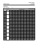
Table 1. Construction Materials
Part Construction Material
Valve Bod
y,
Standard LCC carbon steel
Valve
Body
,
Body Outlet, and Seal Protector
Sour Service Trim
(1)
LCC steel, heat-treated
Body
Outlet,
and
Seal
Protector
Ring or Flow Ring
Optional WCC carbon steel or S31600 [316 stainless steel (SST)]
Drive Shaft Follower Shaft
Standard S17400 (17-4PH SST)
Drive Shaft, Follower Shaft,
and Shaft Retainer
Sour Service Trim
(1)
S17400 (17-4PH SST) H1150 DBL
an
d
Sh
a
ft
R
e
t
a
i
ner
Optional S20910 stainless steel
Standard Chrome-plated WCC steel
Ball
Sour Service Trim
(1)
Chrome-plated WCC steel, heat-treated
Ball
Optional Chrome-plated S31600
Ball Seal All Trims POM (polyoxymethylene)
Bearings All Trims PTFE/Composition-lined S31600
Standard Nitrile
O-Rings
Sour Service Trim
(1)
Fluorocarbon
O Rings
Optional Fluorocarbon
Shaft Seal
Std. with Backup Ring PTFE R30003 / PEEK
Shaft Seal
Live Loaded Packing PTFE / SST
Seal Carrier All Trims S31600 SST
Standard Grade B7 steel
Seal Carrier Stud Bolts
Sour Service Trim
(1)
Grade B7M steel
Seal
Carrier
Stud
Bolts
Optional Grade B8M stainless steel
Standard Grade 2H steel
Seal Carrier Hex Nuts
Sour Service Trim
(1)
Grade 2HM steel
Seal
Carrier
Hex
Nuts
Optional Grade 8M stainless steel
Line Bolts
(2)
Standard Grade B7 steel
Line Bolts
(2)
Sour Service Trim
(1)
Grade B7M steel
Line Nuts
(2)
Standard Grade 2H steel
Line Nuts
(2)
Sour Service Trim
(1)
Grade 2HM
1. As detailed in NACE MR0175-2002.
2. Line bolts and nuts are not included as part of the standard package. Specify line bolts and nuts as an option.
Table 2. Approximate Weights
VALVE SIZE,
WEIGHT
VALVE
SIZE
,
NPS
Kilograms Pounds
4 73 160
6 132 290
8 222 490
10 345 760
12 431 950
16 771 1700
20 1814 4000
24 2404 5300
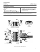
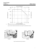
Installation
Install the Design V250 valve in any position, but the
recommended orientation is in a horizontal pipeline
with the shaft positioned horizontally and the ball
closing in the downward direction (see figure 1). The
actuator can be either right- or left-hand mounted as
viewed from the valve inlet for forward-flow. For
bidirectional flow, install the valve so that the highest
pressure condition will flow as shown by the flow
direction arrow on the valve body.
Dimensions are shown in figure 8.