
Data Sheet


V250 Valve
Product Bulletin
51.3:V250
November 2007
3
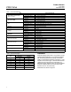
Specifications (continued)
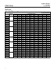
Approximate Weights
See table 2
Options
Line flange bolts, Sour service trim
(3)
,
Buried service actuator adaptation, and Dual
seal configuration for bi-directional shutoff (this
configuration incorporates a tapped and plugged
connection which can be used in a double block
and bleed system to test seal integrity),
Live
Loaded PTFE Packing
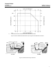
1. The pressure or temperature limits in this bulletin and any applicable standard or code limitations should not be exceeded.
2. The maximum allowable shutoff pressure drops are further limited for the following constructions. The NPS 12 with S20910 drive shaft is limited to 128 bar (1862 psi) from –46 to 59°C (–50
to 139°F) and to 103 bar (1490 psi) at 93°C (200°F). The NPS 16 with 17-4PH steel, with 2-1/2 inch splined driveshaft is limited to 1000 psi (69 bar), and with the S20910, 2-1/2 inch splined
drive shaft is limited to 55 bar (795 psi) at all service temperatures. The NPS 24 with S20910 drive shaft is limited to 92 bar (1336 psi) at all service temperatures.
3. See table 1 for sour service trim materials.
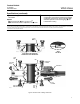
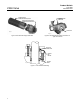
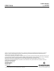
OUTLET
BALL
SEAL
VALVE
BODY
FOLLOWER
SHAFT
SEAL PROTECTOR
RING OR FLOW RING
VALVE
INLET
INLET
BALL
SEAL
SEAL
CARRIER
DRIVE SHAFT
SEE VIEW A
MAIN SHAFT
BEARING
BALL
VIEW A
SEAL DETAIL
OUTLET SIDE OF VALVE BODY FOR
OPTIONAL DUAL SEAL CONSTRUCTION
W7170-1 / IL
W7169-1 / IL
W7169-1 / IL
Figure 2. Sectional View of Design V250 Valve