
Data Sheet
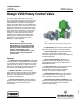


V250 Valve
Product Bulletin
51.3:V250
November 2007
2
Specifications
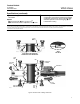
Available Configuration
Flangeless ball valve assembly with
single ball
seal,
flow ring, or dual ball seal
Valve Body Sizes and End Connection Styles
NPS 4 through 12 flangeless valves retained by
line flange bolts and designed to fit between
CL600 or CL900
raised-face or ring-type
joint flanges (ASME B16.5)
NPS 16 through 24 flangeless valves retained by
line flange bolts and designed to fit between
CL600
raised-face or ring-type joint flanges
(ASME B16.5)
Maximum Inlet Pressure
(1)
NPS 4 through 12 consistent with CL600 or
CL900 (ASME B16.34)
NPS 16 through 24 consistent with CL600
(ASME B16.34)
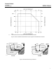
Maximum Allowable Shutoff Pressure Drop
(1,2)
Single-Seal and Dual-Seal Construction: See
figure 3.
Flow Ring Construction: Limited by the
pressure-temperature rating of the valve body
Shutoff Classification
Single-Seal and Dual-Seal Constructions:
0.0001% of maximum valve capacity (less than
1% of Class IV, ANSI/FCI 70-2 and IEC 60534-4)
Flow Ring Construction: 1% of maximum valve
capacity
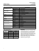
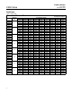
Construction Materials
See table 1
Seal Material Temperature Capability
(1)
Single-Seal and Dual-Seal Construction:
–46 to 82°C (–50 to 180°F) for LCC steel and
CF8M [316 stainless steel (SST)] valve bodies
Flow Ring with Nitrile O-Rings:
–46 to 93°C
(
–50 to 200°F) for LCC steel and CF8M valve
bodies
Flow Ring with Fluorocarbon O-Rings:
–46
to 204°C (
–50 to 400°F) for LCC steel and CF8M
valve bodies
Flow Characteristic
Modified equal percentage
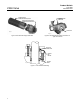
Flow Direction
Single Seal Construction: Forward-flow only
(see figure 4)
Flow Ring Construction: Forward- or
reverse-flow (see figure 4)
Dual Seal Construction: Required to provide
shutoff for bi-directional flow
Flow Coefficients
See the section titled Coefficients in this bulletin,
or see Catalog 12
Noise Levels
See Catalog 12 for sound pressure level
prediction
Maximum Ball Rotation
90 degrees
Actuator Mounting
Right-hand or left-hand mounted as viewed
from the valve inlet for forward-flow
Shaft and Bore Diameters
See figure 8
(continued)