
Instruction Manual

Instruction Manual
D100422X012
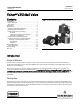
V250 Valve
September 2013
8
Note
The valve shaft's sealing surfaces are critical in obtaining a good seal. If the valve shafts are scratched, nicked or worn, replace or
repair the valve shaft before installing new shaft seals.
Both seal rings, drive end and follower end, should be replaced at the same time.
1. Isolatethecontrolvalvefromthelinepressure,releasepressure from both sides of valve, and drain the process
media from both sides of the valve. For dual seal valve constructions, remove pressure and drain the valve interior
cavity. Shut off and disconnect all lines from the power actuator.
WARNING
Refer to the WARNING at the beginning of the Maintenance section in this instruction manual.
CAUTION
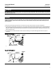
When removing the actuator in the following step, use a wheel puller to separate the actuator parts from the valve shaft.
Failure to do this could cause damage to the actuator parts and the drive shaft.
2. Remove the cap screws (key 29) from the actuator mounting yoke and, while referring to the actuator instruction
manual for assistance, remove the actuator. For oxygen service and hazardous area applications, remove the clamp
and bonding strap assembly (keys 40 and 41, figure 3).
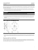
3. Install the new backup ring and shaft seal in the seal carrier. Be sure to install the backup ring on the correct side
(see figure 4).
4. Replace the seal carrier and secure it with the hex nuts (key 8). Be careful not to damage the shaft seal or O-ring
during replacement of the seal carrier.
5. Mount the actuator to the valve while referring to the Actuator Mounting section of this instruction manual and to
the appropriate actuator instruction manual. If appropriate, install or replace the bonding strap assembly and the
clamp (key 41 and 40, figure 3).
Replacing Ball Seal or Flow Ring
Perform this procedure if the control valve is not shutting off properly (that is, leaking downstream). This procedure
does not require removing the actuator from the valve. In addition to being shown in figures 11 and 12, key numbers
areshowninfigure5fortheballsealconstructionsandinfigure6fortheflowringconstruction.
Removal
1. Isolatethecontrolvalvefromthelinepressure,releasepressure from both sides of valve, and drain the process
media from both sides of the valve. For dual seal valve constructions, remove pressure and drain the valve interior
cavity. Shut off and disconnect all lines from the power actuator.
WARNING
Refer to the WARNING at the beginning of the Maintenance section in this instruction manual.