
Instruction Manual

Instruction Manual
D100422X012
V250 Valve
September 2013
6
Maintenance
Valve parts are subject to normal wear and must be inspected and replaced as necessary. The frequency of inspection
and replacement depends upon the severity of service conditions. Instructions are presented in this section for
replacing the shaft seals, the ball seal or flow ring, the drive and follower shafts, the ball and bushing, and the valve
outlet gasket.
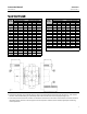
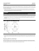
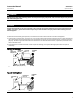
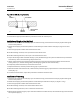
Key number locations are shown in figure 11 for single seal and flow ring constructions, and in figure 12 for dual seal
constructions.
WARNING
Personal injury or property damage can result due to a sudden release of pressure or process fluid if the pipe plug (key 42,
figure 12) is removed while the valve is pressurized. To avoid such injury or damage, remove the pipe plug only when the
control valve is isolated from the pressure system, or provide a hand valve to control r elief of internal valve pressure to
avoid personal injury or property damage.
A V250 valve with a dual seal construction contains a pipe plug port (key 42, figure 12) on the underside of the valve.
This port can be used to relieve internal valve pressure for testing seal integrity when in t he pipeline.
Ifthepipeplugportistobeusedfortestingsealintegritywhenthevalveisinthepipeline,theplugshouldbereplaced
with a hand valve to allow controlled relief of valve pressure during seal leak rate testing.
WARNING
Avoid personal injury or damage to property from sudden release of pressure or uncontrolled process fluid. Before starting
disassembly:
D Do not remove the actuator from the valve while the valve is still pressurized.
D Always wear protective gloves, clothing, and eyewear when performing any maintenance operations to avoid personal
injury.
D Disconnect any operating lines providing air pressure, electric power, or a control signal to the actuator. Be sure the
actuator cannot suddenly open or close the valve.
D Use bypass valves or completely shut off the process to isolate the valve from process pressure. Relieve process pressure
on both sides of the valve. Drain the process media from either side of the valve.
D For dual seal valve constructions, remove pressure and drain the valve interior by removing the pipe plug
(key 42).
D Vent the power actuator loading pressure.
D Use lock-out procedures to be sure that the above measures stay in effect while you work on the equipment.
D The valve packing box may contain process fluids that are pressurized, even when the valve has been removed from the
pipeline. Process fluids may spray out under pressure when removing the packing hardware or packing rings, or when
loosening the packing box pipe plug.
D Check with your process or safety engineer for any additional measures that must be taken to protect against process
media.
Replacing the Follower Shaft Seal
Both the follower and drive shaft seals should be replaced at the same time. Key number locations are shown in figure
11 or 12.