
Instruction Manual

Instruction Manual
D100422X012
V250 Valve
September 2013
5
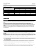
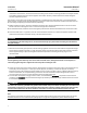
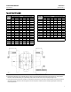
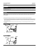
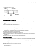
Figure 2. Flange Bolt Lengths
VALVE
SIZE, NPS
CL600 BOLTING DIMENSIONS
Raised Face Flanges Ring Type Joint Flanges
P N M
(1)
P N M
(1)
mm
4 --- --- 343 --- --- 343
6 118 118 413 124 124 413
8 140 137 445 143 140 451
10 159 162 527 165 165 527
12 178 152 584 178 165 584
16 197 197 660 203 203 673
20 254 254 --- 254 254 ---
24 330 330 --- 343 343 ---
Inch
4 --- --- 13.50 --- --- 14.50
6 4.63 4.63 16.25 4.88 4.88 16.25
8 5.50 5.38 17.50 5.63 5.50 17.75
10 6.25 6.38 20.75 6.50 6.50 20.75
12 7.00 6.00 23.00 7.00 6.50 23.00
16 7.75 7.75 26.00 8.00 8.00 26.50
20 10.00 10.00 --- 10.00 10.00 ---
24 13.00 13.00 --- 13.50 13.50 ---
1. These bolts may be installed from either end of the valve.
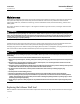
VALVE
SIZE, NPS
CL900 BOLTING DIMENSIONS
Raised Face Flanges Ring Type Joint Flanges
P N M
(1)
P N M
(1)
mm
4 124 124 375 124 130 375
6 127 127 445 127 133 445
8 152 149 483 152 156 483
10 168 171 546 168 175 546
12 184 168 610 184 191 610
20
(2)
--- --- 420 --- --- 420
Inch
4 4.88 4.88 14.75 4.88 5.13 14.75
6 5.00 5.00 17.50 5.00 5.25 17.50
8 6.00 5.88 19.00 6.00 6.13 19.00
10 6.63 6.75 21.5 6.63 6.88 21.50
12 7.25 6.63 24 7.25 7.50 24.00
20
(2)
--- --- 16.5 --- --- 16.5
1. These bolts may be installed from either end of the valve.
2. For NPS 20 size, only studs and nuts are used. See the M dimension.
39A1060-A
A3140-1
10. Attach the bonding strap assembly (key 41, figure 3) to the shaft with the clamp (key 40, figure 3), and connect
the other end of the bonding strap assembly to the valve with the machine screw (key 43, figure 3).
11. Connect pressure lines to the actuator as indicated in the actuator instruction manual. When a manual actuator is
used with a power actuator, install a bypass valve on the power actuator (if not already supplied) for use during
manual operation.