
Instruction Manual

Instruction Manual
D100422X012
V250 Valve
September 2013
4
removed for maintenance, mount the actuator according to the actuator mounting procedure and adjust actuator
travel before inserting t he valve into the pipeline. This allows necessary measurements to be made during the
actuator adjustment process.
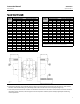
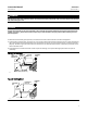
The actuator can be either right-or left-hand mounted, as viewed from the valve body inlet, in any of the positions
shown in figure 10. Refer to the Actuator Mounting procedure in this manual and to the actuator instruction manual
for mounting and adjusting instructions before proceeding.
6. Before installing the valve, make sure the flow through the valve matches the flow direction arrow on the valve.
Failuretodosocandamagethesealinavalvewithasinglesealconstruction.
D For bidirectional flow, install the valve so the highest pressure flow matches the flow direction arrow on t he valve.
D Install the V250 valve in any position, but the recommended orientation is in a horizontal pipeline with the shaft
positioned horizontally and the ball closing in the downward direction.
CAUTION
To avoid damage to the ball sealing surface, rotate the ball to the fully open position before installing the valve between
thepipelineflanges.
7. With the ball in the fully open position, install line flange gaskets and insert the valve between the pipeline flanges.
Use standard composition gaskets, or other flat sheet gaskets compatible with the flow media, between the valve
and t he pipeline flanges. Spiral wound gaskets without compression controlling centering rings are not
recommended.
CAUTION
Uneven tightening of line bolts may cause uneven wear of the ball surface, leakage downstream or to atmosphere, or
uneven flange gasket alignment. Tighten line bolts evenly when installing the valve.
8. Centerthevalveinthelinebymakingsurethematingflangesarealigned.Securethevalveinthelinewiththecap
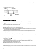
screws (keys 33 and 34, figures 11 and 12), line bolts (key 35, not shown), and hex nuts (key 44, not shown).
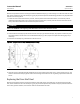
Required clearances for installation of the line bolts and cap screws are shown in figure 2. When tightening the cap
screws and line bolts, use accepted bolting procedures. Lubricate the studs or bolts and tighten the nuts in a
crisscross sequence to ensure proper alignment of the valve with the flanges.
9. For hazardous atmosphere or oxygen service valves, read the following WARNING, and perform the instruction
provided in the WARNING and provide the bonding strap assembly mentioned in Step 10 below if the valve is used
in a hazardous application.
WARNING
The V250 is not necessarily grounded to the pipeline when installed. If the process fluid or the atmosphere around the valve
is flammable, personal injury or property damage could result from an explosion caused by a discharge of static electricity
from the valve components. If the valve is installed in a hazardous area, electrically bond the drive shaft to the valve.
Note
The packing is composed of all conductive packing rings (graphite ribbon packing) to electrically bond the shaft to the valve for
hazardous area service or non-conductive PTFE packing rings. For oxygen service applications, perform the following step.