
Instruction Manual

Instruction Manual
D100422X012
V250 Valve
September 2013
17
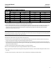
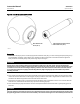
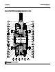
Figure 9. Proper Alignment for Centering the Ball
FG51287-A
A3142
AXIS OF DRIVE SHAFT (KEY 6) AND FOLLOWER SHAFT (KEY 7)
A - B = 0.127 mm (0.005 INCHES) MAX
AB
D Forthefollowershaftsideofthevalve,installseveralbushing spacer shims around the follower shaft and into the
valve. Then, temporarily install the spacer (key 22) and the seal carrier (key 3). Repeat this process, but add only one
more bushing spacer shim into the valve each time, until contact between the seal carrier and the valve is broken.
Then, remove one bushing spacer shim and secure the spacer and seal carrier to the valve with the hex n uts (key 8).
Be careful not to damage the seal (key 16) or O-ring (key 23) during replacement of the seal carrier.
12. Install the seal protector ring (key 14, figure 5) or the flow ring (key 14, figure 6) and all remaining parts by
following the appropriate procedures presented in the Ball Seal and Flow Ring Maintenance section.
13. For NPS 20 CL900 and NPS 24 CL900 valves, lifting hoist rings are provided. If the safety hoist rings were removed,
replacethemandtorquethemto312NSm (230 lbfSft).
14. Mount the actuator to the valve while referring to the actuator mounting section of this instruction manual and to
the appropriate actuator instruction manual. If appropriate, replace the bonding strap assembly and the clamp (key
41 and 40, figure 4).
15. Install the valve into the pipeline by referring to the Installation section of this i nstruction manual.