
Instruction Manual

Instruction Manual
D100422X012
V250 Valve
September 2013
16
equipment. To prevent such damage, make sure that the shaft retainer is tightened to the appropriate torque value listed
in table 4.
5. Apply thread locking adhesive (high strength) (key 30) to the threads of the shaft retainer (key 25). Then, install the
shaft retainer into the inside end of the driveshaft.Tightentheshaftretainertothetorquevaluelistedintable4.
CAUTION
Damage to the valve assembly and downstream equipment could occur if the retainer screw (key 32) should become
disengaged from the follower shaft (key 7) during operation of a V250 control valve assembly. To prevent such damage,
make sure that the internal threads in the inside end of the follower shaft and the external threads of the retainer screw are
cleaned thoroughly before applying thread locking adhesive (high strength) (key 30) as described in step 8 of this assembly
procedure.
6. While maintaining firm support of the ball (key 2), remove the ball support post through the follower shaft bore of
the valve. Then install the follower shaft into the valve. When installing the follower shaft, m ake sure that the drilled
hole containing the two pins (key 9) is aligned with the two notches machined on the inside surface of the ball hub.
7. Temporarily position the follower shaft so that it protrudes slightly into the flow bore of the ball. Place the split ring
(key 31) on the end of the follower shaft. Then, return the follower shaft to its original position.
CAUTION
Improper tightening of the retainer screw (key 32) could allow the retainer screw to become disengaged from the follower
shaft (key 7) during operation of a V250 control valve assembly. This could cause damage to the valve assembly and
downstream equipment. To prevent such damage, make sure that the retainer screw is tightened to the appropriate
torque value listed in table 4.
8. Apply thread locking adhesive (high strength) (key 30) to the threads of the retainer screw. Then, install the retainer
screw into the inside end o f the follower shaft until it i s at least flush with the end surface of the follower shaft. Make
sure that the drilled hole containing the two pins (key 9) is still aligned with the two notches machined on the inside
surface of the ball hub. Tighten the retainer screw to the torque value listed i n table 4.
9. Install the thrust spacer (key 21) into the follower shaft side of the valve and position it so that it is in contact with
the ball hub. Then, install the thrust washer (key 19) and the bushing (key 20).
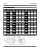
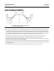
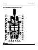
10. Center the ball inside the valve along the axis of both the drive shaft and the follower shaft. The maximum
deviation in measurement between the valve and ball from one side to the other should be no more than 0.005
inches (0.127 mm) as shown in figure 9.
11. In order to maintain proper centering of the ball inside the valve, the bushing spacer shims (key 18) must be
installed in the following manner.
D For the drive shaft side of the valve, install several bushing spacer shims around the drive shaft and into the valve.
Then, temporarily install the spacer (key 22) and the seal carrier (key 17). Repeat this process, but add only one
more bushing spacer shim into the valve each time, until contact between the seal carrier and the valve is broken.
Then, remove one bushing spacer shim and secure the spacer and seal carrier to the valve with the hex n uts (key 8).
Be careful not to damage the seal (key 16) or O-ring (key 23) during replacement of the seal carrier.