
Instruction Manual

Instruction Manual
D100422X012
V250 Valve
September 2013
15
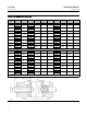
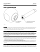
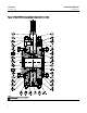
Figure 8. Index Marks on Drive Shaft and Ball
79BA08073-A
B1793
INDEX MARK ON HUB
OF BALL (KEY 2)
INDEX MARK ON POLYGON COUPLING
END OF DRIVE SHAFT (KEY 6)
Assembly
1. Positiontheball(key2)sothatitisfirmlysupportedinsidethevalve(key1).Insertaballsupportpost(seefigure7)
into the follower shaft (key 7) bore of the valve. Position the ball support post so that t he ball will be supported
firmly inside the valve body cavity while performing steps 2 through 5.
CAUTION
Damage to the valve assembly and downstream equipment could occur if the shaft retainer (key 25) should become
disengaged from the drive shaft (key 6) during operation of a V250 control valve assembly. To prevent such damage, make
sure that the internal threads in the Polygon coupling end of the drive shaft and the external threads of the shaft retainer
are cleaned thoroughly before applying thread locking adhesive (high strength) (key 30) as described in step 5 of this
assembly procedure.
2. Insert the drive shaft (key 6) into the drive s haft side of the valve and ball assembly. When inserting the drive shaft,
make sure that the index mark on the Polygon coupling end of the drive shaft is aligned with the index mark on the
hub of the ball. Refer to figure 8 for the location of these index marks.
3. Install the thrust spacer (key 21) into the drive shaft side of the valve and position it so that it is in contact with the
ball hub. Then, install the thrust washer (key 19) and the bushing (key 20).
4. Insert the washer (key 24) into the ball. Lubricate the exposed surface of the washer with a good quality grease or
lubricant.
CAUTION
Improper tightening of the shaft retainer (key 25) could allow the shaft retainer to become disengaged from the drive shaft
(key 6) during operation of a V250 control valve assembly. This could cause damage to the valve assembly and downstream