
Instruction Manual

Instruction Manual
D100422X012
V250 Valve
September 2013
14
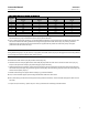
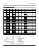
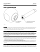
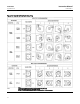
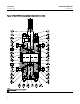
Figure 7. Ball Support Post Dimensions
VALVE SIZE
NPS
A
(1)
B C
(1)
D E F
(2)
G
(1)
H J K
mm
4
41.02
23.83
31.62
146.1 22.23 4
8.69
30.18 7.95 46.05
40.77 31.37 9.04
6
63.25
41.28
50.67
165.1 25.40 4
13.39
46.02 11.13 68.28
62.99 50.42 13.89
8
75.95
50.80
63.37
215.9 34.93 4
16.56
55.58 12.70 85.73
75.69 63.12 17.07
10
85.47
53.98
69.72
215.9 44.45 4
16.56
55.58 15.88 87.33
85.22 69.47 17.07
12
91.82
60.33
76.07
228.6 50.80 4
19.74
65.07 14.30 100.03
91.57 75.82 20.35
16
126.7
82.55
101.3
292.1 66.68 4
26.04
93.68 19.05 138.13
126.4 101.0 26.70
20
152.1
104.8
126.7
336.6 85.73 4
26.04
93.68 23.83 163.53
151.8 126.4 26.70
24
180.6
127.0
152.1
368.3 92.08 4
32.39
136.53 25.40 195.28
180.2 151.8 33.05
Inches
4
1.615
0.938
1.245
5.750 0.875 4
0.342
1.188 0.313 1.813
1.605 1.235 0.356
6
2.490
1.625
1.995
6.500 1.000 4
0.527
1.812 0.438 2.688
2.480 1.985 0.547
8
2.990
2.000
2.495
8.500 1.375 4
0.652
2.188 0.500 3.375
2.980 2.485 0.672
10
3.365
2.125
2.745
8.500 1.750 4
0.652
2.188 0.625 3.438
3.355 2.735 0.672
12
3.615
2.375
2.995
9.000 2.000 4
0.777
2.562 0.563 3.938
3.605 2.985 0.801
16
4.990
3.250
3.990
11.500 2.625 4
1.025
3.688 0.750 5.438
4.975 3.975 1.051
20
5.990
4.125
4.990
13.250 3.375 4
1.025
3.688 0.938 6.438
5.975 4.975 1.051
24
7.110
5.000
5.990
14.500 3.625 4
1.275
5.375 1.000 7.688
7.095 5.975 1.301
1. Tolerances for the A and C dimensions are indicated by showing maximum and minimum dimensions.
2. Numbers of holes in port.
39A1059-B
A3141-1