
Instruction Manual

Instruction Manual
D100422X012
V250 Valve
September 2013
12
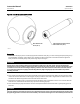
Replacing Drive Shaft, Follower Shaft, Ball, Bushings, and Valve Outlet
Gasket
Thisprocedureistobeperformedtoreplacethevalveball,thedriveshaft,andthefollowershaft,iftheballdoesnot
rotate in response to rotation of the actuator end of the drive shaft, or if there is leakage around the outlet gasket.
Disassembly
CAUTION
When removing the actuator from the valve, do not use a hammer or similar tool to drive the lever off the valve shaft.
Driving the actuator lever off the valve shaft could move the ball (key 2) from the centered position, causing damage to the
ball, the ball seal (key 11), and the valve (key 1).
Use care when removing the actuator lever and, if necessary, use a wheel puller to remove the lever or actuator from the
valve shaft. It is okay to tap the wheel puller screw lightly to loosen the lever or actuator, but hitting the screw with
excessive force could also damage the valve.
1. Remove the cap screws (key 29) from the actuator mounting yoke and, while referring to the actuator instruction
manual for assistance, remove the actuator. If appropriate, remove the clamp and bonding strap assembly (key 40
and 41, figure 3).
2. Remove either the seal protector ring (key 14) or the flow ring (key 14) from the inlet end of the valve assembly by
following steps 1, 2, and 3 of the Replacing Ball Seal or Flow Ring section. For dual seal constructions, note that this
procedure should be repeated on the outlet end of the valve.
3. Proceed as appropriate:
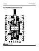
D For single seal constructions and flow ring constructions (figure 11 only), remove the cap screws (key 15).
D Then, remove the valve outlet (key 5) and gasket (key 12).
Note
Perform the following step with the inlet end of the valve assembly facing upward and with the ball (key 2) in the fully open
position.
4. Remove the hex nuts (key 8) from the follower shaft (key 7) side of the valve. Then remove the seal carrier (key 3).
Inspect and replace the seal (key 16) and O-ring (key 23) if necessary.
Note
During the following step, it may be necessary to apply heat to the retainer screw (key 32) to disengage the thread locking
adhesive (high strength) (key 30) that holds the retainer screw in place.
5. Remove the retainer screw (key 32).
6. Using a soft-faced hammer to prevent damaging the end of the follower shaft (key 7), drive the follower shaft into
theflowboreoftheballjustenoughsothatthesplitring (key 31) can be removed. Then remove the split ring.