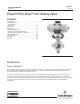
Instruction Manual A81 Valve D103302X012 May 2011 Fisherr POSI‐SEAL™ A81 Rotary Valve Contents Figure 1. Fisher A81 Valve with FieldQ™ Actuator Introduction . . . . . . . . . . . . . . . . . . . . . . . . . . . . . . . . . . . 1 Scope of Manual . . . . . . . . . . . . . . . . . . . . . . . . . . . . 1 Specifications . . . . . . . . . . . . . . . . . . . . . . . . . . . . . . . 2 Description . . . . . . . . . . . . . . . . . . . . . . . . . . . . . . . . . 2 Installation . . . . . . . . . . . . . . . .
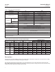
Instruction Manual A81 Valve May 2011 D103302X012 Table 1. Fisher A81 Valve Specifications Specifications EN ASME Valve Body Size DN 50, 80, 100, 150, 200, 250, and 300 NPS 2, 3, 4, 6, 8, 10, and 12 Pressure Rating PN 10 to 40 per EN 12516‐1 CL150 and 300 per ASME B16.34 Valve Body Materials EN 1.0619 steel WCC steel EN 1.4409 stainless steel CF3M (316L) stainless steel CW2M(1) CW2M(1) M35‐2(4) M35‐2 EN 1.
Instruction Manual A81 Valve D103302X012 May 2011 The A81 rotary valve features an eccentrically‐mounted disk with either soft or metal seal, providing capability for enhanced shutoff. The interchangeable sealing technology allows for the same valve body to accept both soft and metal seals. Table 3. Material Temperature Capabilities MATERIAL TEMPERATURE LIMITS(1) EN Materials Valve Body Shaft Bearing Lining and Jacket Seal Packing _C _F 1.
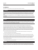
A81 Valve May 2011 Instruction Manual D103302X012 Installation Key numbers in this procedure are shown in figure 9 unless otherwise indicated. WARNING Always wear protective gloves, clothing and eyewear when performing any installation operations to avoid personal injury.
Instruction Manual D103302X012 A81 Valve May 2011 sizes. If piping with a smaller inner diameter than specified above is connected to the valve, measure carefully to be certain the disk rotates without interference before putting the valve into operation. 5. Flow is in the standard direction when the seal retainer (key 2) is facing upstream. Standard flow direction is also indicated by the flow direction arrow cast into the valve body.
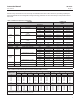
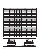
Instruction Manual A81 Valve May 2011 D103302X012 Table 5. Stud Bolt Data WAFER STYLE AND SINGLE FLANGE STYLE WITH THROUGH DRILLED HOLES VALVE SIZE PN 10 PN 16 DN No. of Stud Bolts Size Dia & Thread, mm A Dimen‐ sion, mm 50 4 M16X2 80 8 M16X2 100 8 150 PN 25 No. of Stud Bolts Size Dia & Thread, mm A Dimen‐ sion, mm 125 4 M16X2 140 8 M16X2 M16X2 150 8 8 M20X2.5 160 200 8 M20X2.5 250 12 300 12 No. of Stud Bolts A Dimen‐ sion, mm No.
Instruction Manual D103302X012 A81 Valve May 2011 WARNING An A81 valve body is not necessarily grounded when installed in a pipeline. If the valve is used in a flammable or hazardous atmosphere or for oxygen service, an explosion could result due to a discharge of static electricity from the valve components.
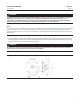
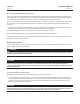
Instruction Manual A81 Valve May 2011 D103302X012 Figure 4. Packing Arrangement Details GE39901‐A PTFE V‐RING GE39986‐A GRAPHITE RIBBON STANDARD PACKING GE40113‐A SINGLE PTFE PACKING GE40118‐A GRAPHITE PACKING ENVIRO‐SEAL PACKING 1 2 3 NOTES: WITH CONDUCTIVE PACKING, THE FEMALE ADAPTOR IN PTFE V‐RING PACKING IS CARBON‐FILLED PTFE. APPLY LUBRICANT. THESE TWO SURFACES SHOULD REMAIN PARALLEL AS YOU ALTERNATELY AND EVENLY TIGHTEN THE PACKING NUTS (KEY 28).
Instruction Manual D103302X012 A81 Valve May 2011 WARNING Avoid personal injury and property damage from sudden release of process pressure or bursting of parts. Before performing any maintenance operations: D Do not remove the actuator from the valve while the valve is still pressurized. D Always wear protective gloves, clothing, and eyewear when performing any maintenance operations. D Disconnect any operating lines providing air pressure, electric power, or a control signal to the actuator.
A81 Valve May 2011 Instruction Manual D103302X012 For valves with the ENVIRO‐SEAL packing system: Optimum performance of the ENVIRO‐SEAL packing system is obtained when the Belleville springs are tightened to their “target load.” The target load is the point where the springs are compressed to 85% of their maximum deflection, or nearly flat. Maximum deflection is when the springs are 100% compressed, or completely flat. Under normal conditions, the packing nuts should not require re‐tightening.
Instruction Manual A81 Valve D103302X012 May 2011 2. Remove the actuator per instructions in separate actuator instruction manuals, then remove the cap screws and nuts (keys 35 and 36). Remove the clamp (key 130, figure 3) if the strap (key 131, figure 3) is used. 3. Remove the packing flange nuts and the packing flange (key 26) if used and pull out the packing follower (key 25). 4. Remove the anti‐blowout ring (key 40) from the drive shaft (key 10). 5.
Instruction Manual A81 Valve May 2011 D103302X012 Figure 5. Orientation of Bearing Tabs BACKSIDE OF VALVE BEARING TAB BEARING TAB 3. Loosen the two packing hex nuts evenly to remove spring tension, then remove the nuts. 4. Remove the packing flange and spring pack assembly. The spring pack assembly consists of the spring stack and packing follower. The spring stack is retained on the packing follower by an O‐ring. Remove the anti‐blowout ring (key 40) from the driveshaft (key 10).
Instruction Manual A81 Valve D103302X012 May 2011 Key numbers in this procedure are shown in figure 9 unless otherwise indicated. 1. Isolate the control valve from line pressure, and relieve pressure from the valve body. Shut off and disconnect all lines from the power actuator. WARNING The edges of a rotating disk have a shearing effect that may result in personal injury. To help prevent such injury, stay clear of the disk edges when rotating the disk (key 3).
Instruction Manual A81 Valve May 2011 D103302X012 1. Isolate the control valve from the line pressure, release pressure from both sides of the valve body, and drain the process media from both sides of the valve. If using a power actuator, also shutoff all pressure lines to the power actuator, release all pressure from the actuator. Use lock‐out procedures to be sure that the above measures stay in effect while you work on the equipment.
Instruction Manual A81 Valve D103302X012 May 2011 Assembly WARNING Do not lubricate bearings that will be used for oxygen service, or where the lubrication is incompatible with the process media. Any use of lubricant can lead to the sudden explosion of media due to the oil/oxygen mixture, causing personal injury or property damage. CAUTION To avoid possible product damage, ensure the bearing tabs are oriented correctly when installing in the following procedure.
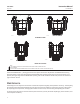
Instruction Manual A81 Valve May 2011 D103302X012 Figure 7. Sectional of Typical Valve Body X2 ACTUATOR END OF SHAFT CCW DISK ROTATION TO OPEN POSITION INDICATION MARK INDICATES APPROXIMATE DISK POSITION X1 Figure 8.
Instruction Manual A81 Valve D103302X012 May 2011 1. If new bearings (key 6) are required, install and orient them in the valve body, as shown in figure 5. Ensure the bearings are fully seated, contacting the inside diameter of the valve body. 2. Insert the disk into the valve body as shown in figure 6, ensuring the “T” stamped on the disk hub is oriented toward the actuator end of the valve body. 3. Install the drive shaft (key 10) through the valve body into the disk.
A81 Valve May 2011 Instruction Manual D103302X012 Actuator Mounting With the valve body out of the line, mount the actuator on the valve body in accordance with the instructions in the actuator instruction manual. Mount the actuator yoke to the valve body, and tighten the actuator‐mounting cap screws and nuts (keys 35 and 36) to the appropriate torque from table 8. Key numbers in this procedure are shown in figure 9 unless otherwise indicated.
Instruction Manual A81 Valve D103302X012 May 2011 Parts Kits Retrofit Kits for ENVIRO‐SEAL Packing Retrofit kits are available for replacing the packing in an existing valve with an ENVIRO‐SEAL packing system. These kits are available for single PTFE or graphite packing. All parts required for installation of the ENVIRO‐SEAL packing system into an existing A81 valve are included in the kits.
Instruction Manual A81 Valve May 2011 D103302X012 Parts List Key Description Note For part numbers not shown, contact your Emerson Process Management sales office. Key Description 1 Valve Body If you need a new valve body, please order by valve size, serial number and desired material.
Instruction Manual A81 Valve D103302X012 May 2011 Figure 9.
Instruction Manual A81 Valve May 2011 D103302X012 Figure 10.
Instruction Manual D103302X012 A81 Valve May 2011 23
A81 Valve May 2011 Instruction Manual D103302X012 Fisher, POSI-SEAL, FieldQ, and ENVIRO‐SEAL are marks owned by one of the companies in the Emerson Process Management business division of Emerson Electric Co. Emerson Process Management, Emerson, and the Emerson logo are trademarks and service marks of Emerson Electric Co. All other marks are the property of their respective owners.