
Instruction Manual


www.Fisher.com
Fisherr Lever-Lock Handlever Actuators
for POSI-SEALt A81 Rotary Valves
Contents
Introduction 1.................................
Scope of Manual 1.........................
Description 1..............................
Specifications 2............................
Installation
3..................................
Ordering Replacements 5.....................
Introduction
Scope of Manual
This instruction manual includes installation,
maintenance, and parts information for the Fisher
Lever-Lock handlever actuator (figure 1). Refer to
separate instruction manuals for information
covering the control valves.
Do not install, operate, or maintain a Lever-Lock
actuator without being fully trained and qualified in
valve, actuator, and accessory installation,
operation, and maintenance. To avoid personal
injury or property damage, it is important to carefully
read, understand, and follow all the contents of this
manual, including all safety cautions and warnings. If
you have any questions about these instructions,
contact your Emerson Process Management sales
office before proceeding.
Description
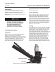
The Lever-Lock handlever is used for reliable
manual operation of DN 50 through 150 (NPS 2
through 6) Fisher A81 high-performance butterfly
valves. Spring-loading secures the handlever in the
notched quadrant plate (figure 2), allowing the valve
disk to be locked in intermediate positions.
Additionally, the handlever can be locked with a
user-supplied padlock with 4.8 to 5.2 mm
(3/16 to 13/64 inch) shackle to prevent accidental or
unauthorized adjustment (see figures 3 and 4).
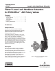
W9585
Figure 1. Fisher Lever-Lock Handlever Actuator
Mounted on Valve
Instruction Manual
D103319X012
May 2009
Lever-Lock Handlever Actuator