Instruction Manual A41 Valve D500211X012 November 2012 Fisherr A41 High Performance Butterfly Valve Contents Introduction . . . . . . . . . . . . . . . . . . . . . . . . . . . . . . . . . . . 1 Scope of Manual . . . . . . . . . . . . . . . . . . . . . . . . . . . . 1 Description . . . . . . . . . . . . . . . . . . . . . . . . . . . . . . . . 1 Specifications . . . . . . . . . . . . . . . . . . . . . . . . . . . . . . 2 Educational Services . . . . . . . . . . . . . . . . . . . . . . . . .
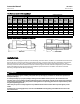
Instruction Manual A41 Valve November 2012 D500211X012 Table 1. Specifications Valve Sizes and End Connection Styles NPS J 2, J 3, J 4, J 6, J 8, J 10, and J 12 valves in wafer or single flanged style (NPS 2 available in wafer style only) Maximum Inlet Pressures(1) Carbon Steel, Stainless Steel, and CN7M Valves: Consistent with CL150 and 300 pressure-temperature ratings per ASME B16.34, unless limited by material temperature capabilities.
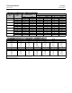
Instruction Manual A41 Valve D500211X012 November 2012 Table 2. Valve Size, Shaft Diameter, and Approximate Weight VALVE SIZE, NPS PRESSURE CLASS 2 3 4 6 8 10 12 APPROXIMATE WEIGHT SHAFT DIAMETER Wafer-Style Single-Flange mm Inches kg Pounds kg Pounds 150/300/600 12.7 1/2 4.3 9.5 --- --- 150 12.7 1/2 4.5 10 6.4 14 300 15.9 5/8 5.9 13 11 25 150 15.9 5/8 8.6 19 11 24 300 19.1 3/4 10 23 18 39 150 19.1 3/4 13 29 16 35 300 25.
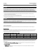
Instruction Manual A41 Valve November 2012 D500211X012 Figure 2. Maximum Pressure/Temperature Ratings DIFFERENTIAL PRESSURE, PSI OPERATING TEMPERATURE, _C PHOENIX III SEAL WITH PTFE INSERT PTFE AND REINFORCED PTFE SEAL UHMWPE SEAL OPERATING TEMPERATURE, _F NOTE: TEMPERATURE LIMITATIONS DO NOT ACCOUNT FOR THE ADDITIONAL 1 LIMITATIONS IMPOSED BY THE BACKUP RING USED WITH THIS SEAL. TO DETERMINE THE EFFECTIVE TEMPERATURE LIMITATION OF THE APPROPRIATE SEAL/BACKUP RING COMBINATION, REFER TO TABLE 4.
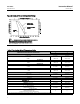
Instruction Manual A41 Valve D500211X012 November 2012 Hex Head Cap Screw and Stud Bolt Data(1) WAFER STYLE VALVE SIZE, NPS CL150 SINGLE FLANGE STYLE CL300 A Dimension, Inch No. of Stud Bolts CL150 Size Dia Inch & Thread A Dimension, Inch No. of Cap Screws CL300 Size Dia Inch & Thread B Dimension, Inch --- --- --- 16 3/4-10 2 2 16 3/4-10 2.25 3/4-10 2 24 3/4-10 2.5 3/4-10 2.25 24 7/8-9 3 24 7/8-9 2.5 32 1-8 3.5 24 7/8-9 2.75 32 1-1/8-8 3.
Instruction Manual A41 Valve November 2012 D500211X012 CAUTION The valve configuration and construction materials were selected to meet particular pressure, temperature, pressure drop, and controlled fluid conditions specified in the customer's order.
Instruction Manual D500211X012 A41 Valve November 2012 b. Phoenix III Seal: This seal is bidirectional. For best performance, high pressure at the closed position should be applied to the back (waterway side) of the disc. c. NPS 2 Seal: The preferred direction of installation is with high pressure at the front (retaining ring side) of the disc. Reverse shutoff is permissible at lower pressure (see specifications table).
A41 Valve Instruction Manual November 2012 D500211X012 D Flange Studs: Install two or more line flange studs into the line flanges to help hold the valve in position while centering the valve. Carefully center the valve on the flanges to ensure disc clearance. D Select and install two pipeline gaskets. D Flange Cap Screws: If line flange cap screws are used, be certain the cap screw threads engage the tapped holes to a depth equal to the flange cap screw diameter. 4.
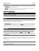
Instruction Manual A41 Valve D500211X012 November 2012 Figure 4. Flow Direction RETAINER RING SIDE RETAINER RING SIDE MFG LABEL MFG LABEL FLOW ARROW ARROW SHOWS PREFERRED FLOW DIRECTION FOR SOFT SEALS AND NPS 2 METAL SEAL FORWARD FLOW FLOW ARROW ARROW SHOWS FLOW DIRECTION FOR NOVEX METAL SEAL, AND PREFERRED FLOW DIRECTION FOR PHOENIX METAL SEAL REVERSE FLOW REVERSE FLOW FORWARD FLOW NOTES: 1. BY EMERSON PROCESS MANAGEMENT DEFINITION: D FORWARD FLOW IS INTO THE FACE SIDE OF THE DISC.
A41 Valve Instruction Manual November 2012 D500211X012 CAUTION It is possible to damage the valve if the actuator travel stops are not properly adjusted before stroking the valve. WARNING Avoid personal injury or property damage from sudden release of process pressure or bursting of parts. Before performing any maintenance operations: D Do not remove the actuator from the valve while the valve is still pressurized.
Instruction Manual A41 Valve D500211X012 November 2012 Figure 5. Optional Shaft-to-Valve Body Bonding Strap Assembly VALVE BODY 37A6528-A A3143-2 VIEW A-A ACTUATOR A A Stopping Leakage For PTFE-filled or graphite standard packing arrangements covered in this manual, often leakage from the packing can be stopped by tightening the packing flange nuts just enough to stop the leak. Use caution when tightening the nuts, overtightened nuts can damage packing box parts.
A41 Valve November 2012 Instruction Manual D500211X012 CAUTION Damage to the disc (key 3) sealing surfaces may occur if the disc is not closed when the valve is being removed from the pipeline. For fail open actuators, it may be necessary to apply loading pressure to the actuator to retain the disc in the closed position while removing the valve from the pipeline. 2. Be sure the disc is in the closed position before attempting to remove the valve from the pipeline or flanges.
Instruction Manual D500211X012 A41 Valve November 2012 Clean all accessible metal parts and surfaces to remove particles that would prevent the packing from sealing. Assembly Inspect the shaft. If it is damaged, it cannot make a good seal with the packing and it must be replaced. If the leakage comes from the outside diameter of the packing, it is possible that the leakage is caused by nicks or scratches around the packing box wall.
Instruction Manual A41 Valve November 2012 D500211X012 Figure 6.
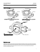
Instruction Manual A41 Valve D500211X012 November 2012 Figure 7. Disc Rotation Indication INDICATES APPROXIMATE DISC POSITION DISC STOP INDICATES APPROXIMATE DISC POSITION TO OPEN ROTATE DISC IN DIRECTION SHOWN ONLY ACTUATOR END OF SHAFT ROTATE DISC IN DIRECTION SHOWN ONLY 2 RETAINER RING (KEY 2) Note: DISC IN THE CLOSED POSITION 2 DISC IN THE OPEN POSITION SET ACTUATOR TRAVEL STOPS TO OBTAIN AN EQUAL DISTANCE T DISC SURFACE AS SHOWN. 2 LOCATION OF C MARKINGS FOR NPS 2 ONLY.
A41 Valve November 2012 Instruction Manual D500211X012 1. Removing the retainer ring (key 2): For valves with press-fit retainer rings: D Place the valve on blocks with the seal retainer facing down. (Note: Position blocks so they do not restrict the retainer ring removal.) D Rotate the disc to the open position as shown in figure 7. D On the seal ring side of the retainer ring, locate one of the knock-out points machined on the retainer ring.
Instruction Manual D500211X012 A41 Valve November 2012 WARNING Do not lubricate parts when used in oxygen service, or where the lubrication is incompatible with the process media. Any use of lubricant can lead to the sudden explosion of media due to the oil/oxygen mixture, causing personal injury or property damage. CAUTION Do not rotate the disc past 90 degrees in the open direction. Rotating the disc past 90 degrees can damage the seal ring or other component parts.
Instruction Manual A41 Valve November 2012 D500211X012 Figure 9.
Instruction Manual D500211X012 A41 Valve November 2012 c. Lay the retainer ring on the valve body. d. Use a press or a soft-faced hammer to press the retainer ring into its groove in the valve body. CAUTION It takes a considerable amount of force with a hammer to drive the retainer ring into place. Be sure not to damage retainer ring surfaces when installing the ring. e. The retainer ring is properly seated when the face of the retainer ring is flush with the face of the valve body. f.
A41 Valve Instruction Manual November 2012 D500211X012 1. Isolate the control valve from line pressure, and relieve pressure from the valve body. Shut off and disconnect all lines from the power actuator. WARNING The edges of a rotating disc have a shearing effect that may result in personal injury. To help prevent such injury, stay clear of the disc edges when rotating the disc (key 3).
Instruction Manual D500211X012 A41 Valve November 2012 Disassembly 1. If necessary, loosen the packing flange nuts (key 101). This allows the drive shaft (key 8) to turn without the friction caused by the packing. 2. Remove the actuator, using the steps provided in the packing maintenance procedures above, and remove the seal ring using the steps provided in the seal ring maintenance procedures above. 3. Place the valve on a flat working surface with the seal ring slot facing down. 4.
Instruction Manual A41 Valve November 2012 D500211X012 Figure 10. Orientation of Bearing/Spacer Tab CENTER LINE OF SHAFT BORE DISC STOP A6357 CENTER LINE OF BODY & DISC SPACER BEARING TAB OR DISC SPACER TAB D For CL150 metal bearings, three piece assemblies: Metal bearings for CL150 valves are an assembly made up of three parts: disc spacer, bearing, and bearing spacer (keys 13, 6, and 7) as shown in the orientation of bearing/spacer tab shown in figure 10. a.
Instruction Manual A41 Valve D500211X012 November 2012 Figure 11. Taper Pin and Hollow Pin Removal and Installation REMOVAL TOOL DIMENSIONS Shaft Diameter A B 12.7 3.91 15.88 INSTALLATION TOOL DIMENSIONS C D Shaft Diameter 28.43 6.35 4.19 12.7 12.7 4.60 38.10 7.87 23.37 15.88 19.05 5.13 44.45 9.65 5.41 25.4 7.00 59.44 12.70 31.75 9.50 76.20 38.1 10.82 44.45 12.37 C D E 3.68 6.35 127.0 4.83 12.7 4.57 7.62 127.0 4.83 19.05 12.7 5.23 8.89 127.0 4.
A41 Valve November 2012 Instruction Manual D500211X012 Installing the Hollow Pin and Taper Pin 4. Place the valve body on a flat working surface with the slot for the seal ring facing up. Block the valve body high enough to allow the disc to be rotated into the open position as shown in figure 11. Note Make sure that the taper pins and hollow pins are free of particulate matter before continuing. 5. Rotate the disc to the open position. Locate the disc position mark on the end of the drive shaft.
Instruction Manual A41 Valve D500211X012 November 2012 5. Unscrew and remove the packing flange nuts (key 12), packing followers (keys 15 and 16), and packing flanges (keys 9 and 10) if used, from both sides of the valve. Table 6.
A41 Valve November 2012 Instruction Manual D500211X012 8. Install the packing according to the appropriate instructions presented in steps 5 through 8 of the Replacing Packing section. 9. Drive in the taper pins securely. 10. Rotate the disc to the closed position. To install the seal ring and complete the assembly, follow the procedures presented in steps 5 through 9 of the Replacing Seal Ring section.
Instruction Manual A41 Valve D500211X012 November 2012 Parts Ordering When corresponding with your Emerson Process Management sales office about this equipment, always mention the valve serial number. When ordering replacement parts, also specify the key number, part name, desired material, using the Parts List table. WARNING Use only genuine Fisher replacement parts.
Instruction Manual A41 Valve November 2012 D500211X012 Repair Kits for ENVIRO-SEAL Packing Repair kits include replacement parts for key 105 and 106 for the shaft diameters listed below. ENVIRO-SEAL Packing Repair Kits SHAFT DIAMETER(1) mm Inches 12.7 1/2 15.9 5/8 19.1 3/4 25.4 1 31.8 1-1/4 38.1 1-1/2 Parts Included in Kit Key Description 105 Packing set 106 Anti-extrusion washer 1. Diameter through the packing box.
Instruction Manual A41 Valve D500211X012 Key 6* 7* 8* 9* 10* 13* Description November 2012 Part Number NPS 6 75B0004X052 NPS 8 75B0012X052 NPS 10 75B0029X052 NPS 12 75B0036X052 Bearing (2 req'd) PEEK/PTFE NPS 2 75B0620X012 NPS 3 CL150 75B1066X012 CL300 75B1073X012 NPS 4 CL150 75B1067X012 CL300 75B1074X012 NPS 6 CL150 75B1068X012 CL300 75B1075X012 PEEK/PTFE NPS 8 CL150 75B1069X012 CL300 75B1076X012 NPS 10 CL150 75B1070X012 CL300 75B1077X012 NPS 12 CL150 75B1071X012 CL300 75B1078X012 316/Nitride NPS
Instruction Manual A41 Valve November 2012 Key Description 1-1/2 inch 1-3/4 inch ENVIRO-SEAL PTFE 1/2 inch 5/8 inch 3/4 inch 1-inch 1-1/4 inch 1-1/2 inch 1-3/4 inch ENVIRO-SEAL Graphite 1/2 inch 5/8 inch 3/4 inch ENVIRO-SEAL Graphite 1-inch 1-1/4 inch 1-1/2 inch 1-3/4 inch KALREZ/PTFE 1/2 inch 5/8 inch 3/4 inch 1-inch 1-1/4 inch 1-1/2 inch KALREZ/CRCC 1/2 inch 5/8 inch 3/4 inch 1-inch 1-1/4 inch 1-1/2 inch 106* Anti-Extrusion Ring, ENVIRO-SEAL PTFE 1/2 inch 5/8 inch 3/4 inch 30 D500211X012 Part Numbe
Instruction Manual A41 Valve D500211X012 November 2012 Key 2*.
Instruction Manual A41 Valve November 2012 D500211X012 Key 9*.
Instruction Manual A41 Valve D500211X012 November 2012 Figure 12. Wafer Valve Assembly for the NPS 3 through 12 ALLOY FOLLOWER ASSY PTFE SEAL METAL BEARING CL150 NOVEX SEAL SIZE 12 CL300 PHOENIX III SEAL NOTE: KEYS 21, 22, AND 28 ARE NOT SHOWN.
Instruction Manual A41 Valve November 2012 D500211X012 Figure 12.
Instruction Manual A41 Valve D500211X012 November 2012 Figure 13.
A41 Valve November 2012 Instruction Manual D500211X012 Neither Emerson, Emerson Process Management, nor any of their affiliated entities assumes responsibility for the selection, use or maintenance of any product. Responsibility for proper selection, use, and maintenance of any product remains solely with the purchaser and end user. Fisher and ENVIRO-SEAL are marks owned by one of the companies in the Emerson Process Management business unit of Emerson Electric Co.