
Data Sheet


A11 Valve
D500203X012
Product Bulletin
21.1:A11
May 2013
8
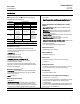
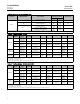
Table 7. Valve/Actuator Combinations
TEMPERATURE RANGE
SELECTION GUIDELINES
1052, 1061, or 2052
(1, 2)
Bettis™
(3)
, FieldQt
(5)
, 1035
(5)
,orHytorkXL
-254 to -196_C
(-425 to -320_F)
Valve with cryogenic extension and special trim
materials
(4)
and standard actuator
Valve with cryogenic extension and special trim
materials
(4)
and standard actuator
-196 to -46_C
(-320 to -50_F)
Valve with cryogenic extension and trim and
standard actuator
Valve with cryogenic extension and trim and
standard actuator
-46 to 343_C
(-50 to 650_F)
Valve (select appropriate trim) and standard
actuator
Valve (select appropriate trim) and standard
actuator
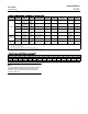
343 to 426_C
(650 to 800_F)
Mounting positions 1 and 3: Valve (select
appropriate trim) and standard actuator
Mounting positions 2 and 4: Valve with 6-inch
extension (select trim 514H or 564H) and
standard actuator - ambient temperature may
dictate the need for a high-temperature
diaphragm
Valve (select appropriate trim) and actuator with
high-temperature O-rings option
or
Valve with 6-inch extension (select trim 514H)
and standard actuator
426 to 538_C
(800 to 1000_F)
Mounting positions 1 and 3: Valve (select
appropriate trim) and standard actuator
Mounting positions 2 and 4: Valve with 6-inch
extension (select trim 564H or 514H with N07718
shaft) and standard actuator - ambient
temperature may dictate the need for a
high-temperature diaphragm
Valve (select appropriate trim) and actuator with
high-temperature O-rings option
or
Valve with 6-inch extension (select trim 564H or
514H with N07718 shaft) and standard actuator
538 to 816_C
(1000 to 1500_F)
Valve with 12-inch extension and special trim
materials
(4)
and standard actuator
Valve with 12-inch extension and special trim
materials
(4)
and standard actuator
1. Select splined shaft option when necessary (standard for NPS 3-12 CL600 valves).
2. See figure 2 for actuator mounting positions.
3. Select keyed shaft option when using Bettis “G” Series Actuator, NPS 6-12.
4. Consult your Emerson Process Management sales o ffice.
5. Select square shaft option when using FieldQ or 1035 actuators.
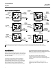
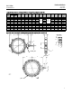
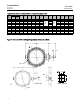
Figure 2. Mounting Styles and Positions
STYLE A
STYLE C
STYLE B
STYLE D
POSITION 1
STANDARD
NORMAL
FLOW
POSITION 1
STANDARD
2
3
4
2
3
4
POSITION 1
STANDARD
POSITION 1
STANDARD
4
4
33
2
2
NORMAL
FLOW
GE37285