
Data Sheet
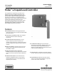


L2 Controller
D103034X012
Product Bulletin
34.2:L2
September 2013
2
Specifications
Available Configurations
Controllers: Snap-acting or throttling
Sensor: Displacer-type liquid level sensor for
mounting to side of tank. Displacer travel is
transmitted to controller by pivotal movement of
displacer rod
Input Signal
Type: Liquid level or liquid-to-liquid interface
Level Change Required for Full Change in Output
Signal in a 1.0 Specific Gravity Liquid, with 1.4 bar (20
psig) Supply Pressure, Direct Action, and Standard
1-7/8 X 12-Inch (48 x 305 mm) Vertical Displacer with
Standard Lever Arm Length:
Control Mode
Minimum Span Level
Change, mm (Inches)
(1)
Maximum Span Level
Change, mm (Inches)
(1)
Throttling 102 (4) 305 (12)
On-off 127 (5) 305 (12)
Snap-acting 13 (0.5) 20 (0.8)
Minimum Specific Gravity
(2)
Throttling Controller: Minimum specific gravity, or
specific gravity differential for interface applications,
is 0.1
(3)
.
Snap-Acting Controller: Minimum specific gravity, or
specific gravity differential for interface applications,
is 0.1
Output Signal
Pneumatic
J on-off or J proportional pressure
signal
Ranges:
Throttling:
J 0.2 to 1.0 bar (3 to 15 psig) or J 0.4 to
2.0 bar (6 to 30 psig)
On-Off: 0 (off) or full supply pressure (on)
Action: Field-reversible between direct (increasing
level increases output signal) and reverse (increasing
level decreases output signal)
Supply Pressure Requirements
Throttling Controller:
Throttling: 1.4 bar (20 psig) for 0.2 to 1.0 bar (3 to 15
psig) output signal and 2.4 bar (35 psig) for 0.4 to 2.0
bar (6 to 30 psig) output signal
On-Off: Any desired pressure between 1.4 and 3.4 bar
(20 and 50 psig)
Snap-Acting Controller: Any desired pressure
between 1.4 and 5.2 bar (20 and 50 psig) direct, and
1.4 and 2.4 bar (20 and 35 psig) reverse
Do not use supply pressure below 1.4 bar (20 psig)
Supply Pressure Medium
Air or natural gas
(4)
Steady-State Air Consumption
(5)
Throttling Controller: ≤0.03 normal m
3
/hr (1.0 scfh)
at 1.4 bar (20 psig) supply pressure
Snap-Acting Controller: ≤0.03 normal m
3
/hr
(1.0 scfh) at 1.4 bar (20 psig) supply pressure or
≤0.04 normal m
3
/hr (1.5 scfh) at 2.4 bar (35 psig)
supply pressure in tripped condition; air consumption
increases during trip
Sensor to Vessel Connection
J 2 NPT threaded or J NPS 2 CL150 through 1500
slip-on flange connection
(6)
Controller Connections
Supply: 1/4 NPT internal located on the bottom of the
case
Output: 1/4 NPT internal located on the top of the
case
Case Vent: 1/4 NPT internal with vent screen
assembly located on the back of the case
Standard Displacer Size
48 x 305 mm, 541 cm
3
(1-7/8 x 12 inches, 33 in
3
)
Maximum Displacer Insertion Length
(7)
Standard lever arm length plus one 6-inch extension,
horizontal or vertical
Displacer Material and Maximum Sensor Working
Pressure
(8)
PVC Displacer: Consistent with CL1500 pressure
temperature ratings per ASME B16.34 up to
maximum pressure of 258.5 bar (3750 psig)
For PED (97/23/EC) maximum pressure limited to 200
bar (2900 psig)
S31603 SST Displacer: CL600 pressure temperature
ratings per ASME B16.34 up to maximum pressure of
99.3 bar (1440 psig)
Note: For slip-on flange connection, maximum sensor
working pressure must be consistent with the flange
ratings
-continued-