
Data Sheet


EH and EHA Valves
D100042X012
Product Bulletin
51.2:EH
April 2015
10
Principle of Operation
(NPS 8 through 14 Globe Valves)
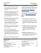
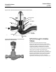
EHD and EHT valves, shown in figures 8 and 10, are
balanced valve designs. When the valves are opening
or closing, pressure registers on top of the valve plug
through the balancing holes in the plug. The force of
the pressure on top of the plug balances the force of
the pressure on the bottom of the plug to reduce the
actuator force required.
W4426-1
RETAINING
RINGS
BACKUP
RING
PRESSURE-
ASSISTED
SEAL
RING
Figure 10. Fisher EHT Trim (NPS 8 through 14 Globe
Valves)
FLOW
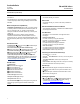
Figure 11. Fisher EHD Trim with Whisper Trim III
Level D Cage (NPS 8 through 14 Globe Valves)
W4428-1
FLOW
Figure 12. Diverter Cone Valve Plug Used in Fisher
EHD and EHT Valves (NPS 8 through 14 Globe Valves,
Flow Up Only)
W4430-1
DIVERTER
CONE
DIVERTER CONE VALVE PLUG USED IN BOILER FEEDWATER
SERVICE FOR FLOWING ΔP> 1000 PSI (69 BAR) AND IN
OTHER APPLICATIONS FOR FLOWING ΔP> 138 BAR (2000
PSI) OR FOR WHISPER TRIM III LEVEL A, B, OR C CAGES
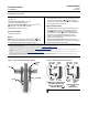
Figure 13. Seat Ring Gasket Constructions
(NPS 8 through 14 Globe Valves)
O-RING GASKET CONSTRUCTION
(STANDARD CONSTRUCTION FOR SOUR SERVICE AND
OPTIONAL FOR OTHER VALVE CONSTRUCTIONS)
SEAT
RING
VALVE
BODY
SEAT RING
CAP SCREW
SPIRAL
WOUND
GASKET
SEAT
RING
VALVE
BODY
SEAT RING
CAP SCREW
O-RING
W4429-1
SPIRAL WOUND GASKET CONSTRUCTION
(STANDARD CONSTRUCTION FOR HIGH TEMPERATURE
APPLICATIONS)