Instruction Manual EH Valves NPS 8 through 14 D100392X012 July 2014 Fisherr EHD and EHT NPS 8 through 14 Sliding-Stem Control Valves Contents Introduction . . . . . . . . . . . . . . . . . . . . . . . . . . . . . . . . . 1 Scope of Manual . . . . . . . . . . . . . . . . . . . . . . . . . . . . . 1 Description . . . . . . . . . . . . . . . . . . . . . . . . . . . . . . . . . 2 Specifications . . . . . . . . . . . . . . . . . . . . . . . . . . . . . . . 2 Educational Services . . . . . . . . . . . . . . .
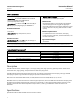
Instruction Manual EH Valves NPS 8 through 14 D100392X012 July 2014 Table 1. Specifications End Connection Styles(1) Buttwelding: All available ASME B16.25 schedules that are compatible with ASME B16.34 pressure/temperature ratings Flanged Ends: CL1500 or 2500 J raised-face (RF) or J ring-type joint (RTJ) flanges per ASME B16.5 Shutoff Classifications See table 2 Bore seal trim: High-temperature, Class V.
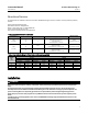
Instruction Manual EH Valves NPS 8 through 14 D100392X012 July 2014 Educational Services For information on available courses for the Fisher EH NPS 8 through 14 valve, as well as a variety of other products, contact: Emerson Process Management Educational Services - Registration Phone: 1-641-754-3771 or 1-800-338-8158 E-mail: education@emerson.com http://www.emersonprocess.com/education Table 3.
EH Valves NPS 8 through 14 Instruction Manual July 2014 D100392X012 CAUTION The valve configuration and construction materials were selected to meet particular pressure, temperature, pressure drop, and controlled fluid conditions. Because some body/trim material combinations are limited in their pressure drop and temperature range capabilities, do not apply any other conditions to the valve without first contacting your Emerson Process Management sales office.
Instruction Manual EH Valves NPS 8 through 14 D100392X012 July 2014 Principle of Operation Key numbers referenced in this section are shown in figure 12 for the EHD valve and in figure 14 for the EHT valve. EHD and EHT valves are balanced designs. When they are opening or closing, pressure registers on top of the valve plug (key 3) through the registration holes in the plug.
Instruction Manual EH Valves NPS 8 through 14 D100392X012 July 2014 8. After all maintenance is complete, refer to the Trim Replacement procedure to assemble the valve body. Note If the valve has ENVIRO-SEAL™ live-loaded packing installed, see the Fisher instruction manual titled ENVIRO-SEAL Packing System for Sliding-Stem Valves (D101642X012) for packing instructions.
Instruction Manual EH Valves NPS 8 through 14 D100392X012 July 2014 A lubricator or lubricator/isolating valve (figure 2) is recommended for PTFE-impregnated composition packing. The lubricator or lubricator/isolating valve is installed in place of the pipe plug in the bonnet. Use a good quality silicon-base lubricant. Do not lubricate packing used in oxygen service or in processes with temperatures over 260_C (500_F).
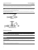
Instruction Manual EH Valves NPS 8 through 14 D100392X012 July 2014 Key numbers referred to in this procedure are shown in figure 11 unless otherwise indicated. 1. Remove the stem connector cap screws shown in figure 3, and separate the two halves of the stem connector. Then exhaust all actuator pressure, if any was applied, and disconnect the actuator supply and any leakoff piping. 2. Remove the hex nuts (key 26) and remove the actuator from the bonnet (key 1).
Instruction Manual EH Valves NPS 8 through 14 D100392X012 July 2014 injury. Use a stick or other device to thread a rope or sling through the windows. Use this rigging to secure the cage to the bonnet or hoist to prevent damage or injury should the cage suddenly separate from the bonnet. CAUTION When lifting the bonnet (key 1), be sure that the valve plug and stem assembly (keys 3 and 4, figure 12 or 14) remains on the seat ring (key 6, figure 12 or 14).
Instruction Manual EH Valves NPS 8 through 14 D100392X012 July 2014 Figure 4.
Instruction Manual D100392X012 EH Valves NPS 8 through 14 July 2014 12. Slide the bonnet over the stem and onto the bonnet studs (key 13, figure 12 or 14). Note Proper performance of the bolting procedures in step 13 compresses the cage gaskets (key 11, figure 12 or 14) enough to seal the body-to-bonnet joint. The prelubricated hex nuts (key 14, figure 12 or 14) referred to in step 13 can be identified by a black film coating on the nut threads.
Instruction Manual EH Valves NPS 8 through 14 D100392X012 July 2014 For spring-loaded PTFE V-ring packing: Tighten the packing flange nuts until the shoulder on the packing follower (key 13) contacts the bonnet (key 1). For other kinds of packing, except ENVIRO-SEAL and HIGH-SEAL: Tighten the packing flange nuts to the maximum recommended torque shown in table 5. Then, loosen the packing flange nuts and retighten them to the recommended minimum torque in table 5.
Instruction Manual EH Valves NPS 8 through 14 D100392X012 July 2014 1. With the valve plug (key 3) removed per the Trim Removal procedure, proceed as appropriate: For the EHD valve, the piston rings (key 8) are each in two sections; remove the sections from the grooves in the valve plug. For all EHT valves, work the retaining ring (key 10) off the valve plug with a screwdriver. Carefully slide the backup ring and seal ring (keys 9 and 8) off the valve plug.
EH Valves NPS 8 through 14 Instruction Manual July 2014 D100392X012 5. After lapping, again disassemble as necessary, clean the seating surfaces, reassemble, and test for shutoff. Repeat the lapping procedure if necessary. Trim Replacement After all trim maintenance has been completed, reassemble the valve by following the numbered steps below. Be certain that all gasketed surfaces are clean.
Instruction Manual D100392X012 EH Valves NPS 8 through 14 July 2014 6. Install the valve plug into the cage. 7. Install the other cage gasket (key 11) between the cage and the bonnet. CAUTION Failure to comply with good bonnet-to-body bolting practices and the torque values shown in table 6 may result in cage crushing, cage diameter reduction, and/or bonnet deformation. Cheater bars or slug wrenches should not be used for this procedure.
Instruction Manual EH Valves NPS 8 through 14 D100392X012 July 2014 Figure 5.
Instruction Manual EH Valves NPS 8 through 14 D100392X012 July 2014 Retrofit: Installing Bore Seal Trim Note Additional actuator thrust is required for a valve with Bore Seal trim. When installing Bore Seal trim in an existing valve, contact your Emerson Process Management sales office for assistance in determining new actuator thrust requirements.
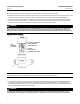
Instruction Manual EH Valves NPS 8 through 14 D100392X012 July 2014 Figure 6. Bore Seal Installation Tool E F A B G C H D GE22109-A Table 8. Bore Seal Installation Tool Dimensions VALVE PORT SIZE, INCH 5.375 A B C D E F G H Tool Part Number 5.49 5.07 5.17-5.19 5.39-5.37 0.10 0.10 0.32 R.06 GE22109X012 7.00 7.11 6.69 6.79-6.81 7.01-6.99 0.09 0.10 0.32 R.06 GE18264X012 10.00 10.12 9.7 9.80-9.82 10.02-10.00 0.10 0.10 0.32 R.
Instruction Manual EH Valves NPS 8 through 14 D100392X012 July 2014 CAUTION To avoid excessive leakage and seat erosion, the valve plug must be initially seated with sufficient force to overcome the resistance of the Bore Seal plug seal and contact the seat ring. You can correctly seat the valve plug by using the same force calculated for full load when sizing your actuator.
Instruction Manual EH Valves NPS 8 through 14 D100392X012 July 2014 Figure 7. Stake the Threads of the Bore Seal Retainer DEFORM THREAD TO STAKE Bore Seal RETAINER Figure 8.
Instruction Manual EH Valves NPS 8 through 14 D100392X012 July 2014 D The open interior of the Bore Seal plug seal must face up in a valve with flow-up construction (figure 5). D The open interior of the Bore Seal plug seal must face down in a valve with flow-down construction (figure 5). Figure 9.
EH Valves NPS 8 through 14 July 2014 Instruction Manual D100392X012 Actuator Mounting The following procedure assumes that the valve and actuator are fully assembled, but with the actuator removed from the valve. Unless otherwise identified, the parts involved in making up the actuator-valve stem connection are shown in figure 3. CAUTION Never use a wrench or pliers on the valve plug stem and never turn the valve plug stem while the valve plug assembly is seated.
Instruction Manual EH Valves NPS 8 through 14 D100392X012 July 2014 Parts Kits ENVIRO-SEAL Packing Retrofit Kits Retrofit kits include parts to convert existing packing to the ENVIRO-SEAL packing system. PTFE kits include keys 200, 201, 211, 212, 214, 215, 217, 218, tag, and cable tie. Graphite kits include keys 200, 201, 207, 208, 209, 210, 211, 212, 214, 216, 217, tag, and cable tie. Duplex kits include keys 200, 201, 207, 209, 211, 212, 214, 215, 216, 217, tag, and cable tie.
Instruction Manual EH Valves NPS 8 through 14 D100392X012 July 2014 Figure 10.
Instruction Manual EH Valves NPS 8 through 14 D100392X012 July 2014 Figure 11. Bonnet Assembly 35A3976-A Parts List Note Part numbers are shown for recommended spares only. For part numbers not shown, contact your Emerson Process Management sales office. Bonnet Assembly (figures 4 and 11) Key 1 3 4 5 6* 7* Description Bonnet If you need a bonnet as a replacement part, order by valve size and stem diameter, serial number, and desired material.
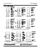
Instruction Manual EH Valves NPS 8 through 14 D100392X012 July 2014 Keys 6, 7, 9, 12, 30, 31 and 32 Soft Packing Parts* VALVE STEM CONNECTION mm Inches PACKING ARRANGEMENT KEY NUMBER PACKING PART DESCRIPTION QUANTITY PART NUMBER PTFE, single packing 6 31 32 7 30 12 Packing set (includes keys 7, 30, 31 & 32) Male Adapter Female Adapter V-ring Lower Wiper Upper Wiper 1 1 1 3 1 1 1R290801012 1H995701012 1H995801012 1D387601012 1J872506992 1J873006332 2 1R290801012 31 32 7 30 12 Packing set (i
Instruction Manual EH Valves NPS 8 through 14 D100392X012 July 2014 Valve Assembly (figures 12, 13, and 14) Key Description Part Number Key 9* 1 2* 3* 4* 5* 6* 7 8* 8* Valve Body If you need a valve body as a replacement part, order by valve size, serial number, and desired material. Cage Valve Plug Valve Plug Stem Pin, stainless steel For use with 31.8 mm (1-1/4 inch) valve plug stem For use with 50.
Instruction Manual EH Valves NPS 8 through 14 D100392X012 July 2014 Figure 12.
Instruction Manual EH Valves NPS 8 through 14 D100392X012 July 2014 Figure 13.
Instruction Manual EH Valves NPS 8 through 14 D100392X012 July 2014 Figure 14.
Instruction Manual EH Valves NPS 8 through 14 D100392X012 Key Description 11* 12* 12* 13 July 2014 Part Number Cage Gasket (2 req'd) For standard service, silver pl N04400 NPS 8 and 10 valves CL1500 CL2500 NPS 12 and 14 valves CL1500 CL2500 For sour gas service, tin pl N04400 NPS 8 and 10 valves CL1500 CL2500 NPS 12 and 14 valves CL1500 CL2500 Seat Ring Gasket Spiral wound N06600 NPS 8 and 10 valves CL1500 CL2500 NPS 12 and 14 valves CL1500 CL2500 Seat Ring O-Ring NPS 8 and 10 valves CL1500 Nitri
Instruction Manual EH Valves NPS 8 through 14 D100392X012 July 2014 Key 2* Whisper Trim III Cage VALVE SIZE, NPS CAGE CONSTRUCTION CL1500 Rating CL2500 Rating 17-4PH STAINLESS STEEL WITH H1150 DBL HEAT-TREATMENT FOR SOUR GAS SERVICE CL1500 Rating CL2500 Rating 8, 10 Level A1 Level A3 Level B1 Level B3 Level C1 Level C3 Level D1(1) Level D3(1) 30B1118X012 30B1120X012 30B1122X012 30B1124X012 30B1126X012 30B1128X012 30B1185X012 30B1185X022 30B1130X012 30B1132X012 30B1134X012 30B1136X012 30B1138X012
Instruction Manual EH Valves NPS 8 through 14 D100392X012 July 2014 Key 3* Valve Plug for NPS 8 or 10 Fisher EHD with Whisper Trim III Cage MATERIAL 17-4PH stainless steel, H900 heat-treated OPERATING TEMPERATURE LIMITS _C _F -29 to 427 -29 to 149 93 to 204 149 to 260 204 to 316 316 stainless steel, alloy 6 (CoCr-A) seat and guide 260 to 371 316 to 427 371 to 482 427 to 538 482 to 593 -29 to 232 N06600, alloy 6 (CoCr-A) seat and guide 233 to 427 428 to 593 17-4 stainless steel, H1150 heat-treated,
Instruction Manual EH Valves NPS 8 through 14 D100392X012 July 2014 Key 3* Valve Plug for NPS 12 or 14 Fisher EHD with Whisper Trim III Cage MATERIAL 17-4PH stainless steel, H900 heat-treated OPERATING TEMPERATURE LIMITS _C _F -29 to 427 -29 to 149 93 to 204 149 to 260 204 to 316 316 stainless steel, alloy 6 (CoCr-A) seat and guide 260 to 371 316 to 427 371 to 482 427 to 538 482 to 593 -29 to 232 N06600, alloy 6 (CoCr-A) seat and guide 233 to 427 428 to 593 17-4 stainless steel, H1150 heat-treated
Instruction Manual EH Valves NPS 8 through 14 D100392X012 July 2014 Key 3* Valve Plug for Fisher EHT with Whisper Trim III Cage VALVE SIZE, NPS MATERIAL 17-4 stainless steel, H1075 heat-treated OPERATING TEMPERATURE LIMITS _C _F -29 to 232 -29 to 149 316 stainless steel, alloy 6 (CoCr-A) seat and guide 93 to 204 149 to 232 8, 10 N06600, alloy 6 (CoCr-A) seat and guide 17-4 stainless steel, H1150 heat-treated, alloy 6 (CoCr-A) seat and guide 17-4 stainless steel, H1150 DBL heat-treated, alloy 6 (Co
Instruction Manual EH Valves NPS 8 through 14 D100392X012 July 2014 Key 4* Valve Plug Stem for NPS 8 or 10 Fisher EHD or EHT Valve without Whisper Trim III Cage VALVE RATING VALVE DESIGN VALVE STEM CONNECTION mm Inches CL2500 EHT 36 Noncoated Cr Ct Noncoated Cr Ct 316 Stainless Steel S20910 1-1/4 100, 101 404 405 406 407 76 89 89 89 89 3 3.5 3.5 3.5 3.
Instruction Manual EH Valves NPS 8 through 14 D100392X012 July 2014 Key 4* Valve Plug Stem for NPS 12 or 14 Fisher EHD or EHT Valve without Whisper Trim III Cage VALVE RATING VALVE DESIGN VALVE STEM CONNECTION mm EHD and EHT Inches Noncoated Cr Ct Noncoated Cr Ct 316 Stainless Steel S20910 1-1/4 404 405, 406 407 802 490 102 102 102 114 114 4 4 4 4.5 4.
Instruction Manual EH Valves NPS 8 through 14 D100392X012 July 2014 Key 4* Valve Plug Stem for Valve with Whisper Trim III Cage MATERIAL ACTUATOR GROUP VALVE SIZE, NPS STEM DIAMETER VALVE RATING TRAVEL Noncoated Cr Ct 13A4764X262 29A9092X012 13A4764X272 --- 19A9044X012 --- 13A4764X282 29A9092X022 --29A9093X012 5.75 5.75 13A4764X292 29A9092X032 13A4764X302 --- 19A9094X022 --- 13A4764X312 29A9092X042 --29A9093X022 184 184 7.25 7.
Instruction Manual EH Valves NPS 8 through 14 D100392X012 July 2014 Key 6* Seat Ring and Key 7 Cap Screw for Valve with Gasket Construction and Whisper Trim III Cage VALVE SIZE, NPS 8, 10 MATERIAL Part Number Cap Screw 17-4PH stainless steel, H1075 heat-treated SA-564, H1100 heat-treated CL1500 39A7400X032 19A7492X022 CL2500 39A7402X032 19A7493X022 SA-564, H1100 heat-treated CL1500 39A7401X122 19A7492X022 CL2500 39A7403X122 19A7493X022 SA-453-660, CLA CL1500 39A7401X032 19A7492X03
Instruction Manual EH Valves NPS 8 through 14 D100392X012 July 2014 Key 6* Seat Ring and Key 7 Cap Screw for Valve with O-Ring Construction and without Whisper Trim III Cage VALVE SIZE, NPS 8, 10 12, 14 40 MATERIAL KEY 7 CAP SCREW VALVE RATING KEY 6 SEAT RING Part Number Seat Ring Cap Screw 17-4PH stainless steel, H1075 heat-treated SA-564, H1100 heat-treated CL1500 39A9035X022 19A7492X022 CL2500 39A9037X022 19A7493X022 316 stainless steel, alloy 6 (CoCr-A) seat SA-453-660, CLA CL15
Instruction Manual EH Valves NPS 8 through 14 D100392X012 July 2014 Key 6* Seat Ring and Key 7 Cap Screw for Valve with O-Ring Construction and Whisper Trim III Cage VALVE SIZE, NPS MATERIAL KEY 7 CAP SCREW VALVE RATING KEY 6 SEAT RING Part Number Seat Ring Cap Screw 17-4PH stainless steel, H1075 heat-treated SA-564, H1150 heat-treated CL1500 39A9035X022 19A7492X022 CL2500 39A9037X022 19A7493X022 SA-564, H1100 heat-treated CL1500 39A9036X062 19A7492X022 CL2500 39A9038X062 19A7493X0
Instruction Manual EH Valves NPS 8 through 14 D100392X012 July 2014 Actuator Groups by Type Number Group 100 127 mm (5-Inch) Yoke Boss 472 473 474 476 585C 657 1008 Group 101 127 mm (5-Inch) Yoke Boss 667 Group 404 127 mm (5-Inch) Yoke Boss 667 667-4 Group 405 127 mm (5-Inch) Yoke Boss 657 MO 657-4 MO 42 Group 406 127 mm (5-Inch) Yoke Boss 667 MO 667-4 MO Group 407 127 mm (5-Inch) Yoke Boss 474 585C 657 Group 408 127 mm (5H) and 178 mm (7-Inch) Yoke Boss 657 Size 100 1008 Group 409 127 mm (5H) and 17
Instruction Manual D100392X012 EH Valves NPS 8 through 14 July 2014 43
EH Valves NPS 8 through 14 July 2014 Instruction Manual D100392X012 Neither Emerson, Emerson Process Management, nor any of their affiliated entities assumes responsibility for the selection, use or maintenance of any product. Responsibility for proper selection, use, and maintenance of any product remains solely with the purchaser and end user. Fisher, Whisper Trim, Cavitrol, and ENVIRO-SEAL are marks owned by one of the companies in the Emerson Process Management business unit of Emerson Electric Co.