
Instruction Manual
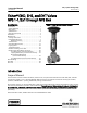


Instruction Manual
D100394X012
EH (1-1/2x1 through 8x6)
December 2014
8
Replacing Packing
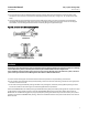
Key numbers referred to in this procedure are shown i n figure 16 unless otherwise indicated.
1. Isolatethecontrolvalvefromthelinepressure,releasepressure from both sides of the valve body, and drain the
process media from both sides of the valve.
Remove the cap screws in the stem connector, and separate the two halves of the stem connector. Then exhaust all
actuator pressure, if any was applied, and disconnect the actuator supply and any leakoff piping.
2. Removeeithertheyokelocknut(key15)orthehexnuts(key26),andremovetheactuatorfromthebonnet(key1).
3. Loosen the packing flange nuts (key 5) so that the packing is not tight on the valve plug stem (key 4, figure 17, 18,
or 20). Remove any travel indicator disk and stemlocknutsfromthevalveplugstemthreads.
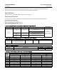
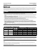
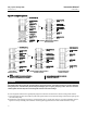
Table 8. Torque for Body-to-Bonnet Bolting Using Anti-Seize Lubricant(1)
VALVE
SIZE,
NPS
VALVE
BODY
RATING
TORQUE
NSm LbfSFt
B7, B16, BD and 660 Studs B8 and B8M Studs B7,B16,BDand660Studs B8 and B8M Studs
1, 1-1/2 x 1, 2x1
CL1500 163 122 120 90
CL2500 258 195 190 140
2, 3x2
CL1500 258 195 190 140
CL2500 380 285 280 210
3, 4x3
CL1500 556 420 410 310
CL2500 786 597 580 440
4, 6x4
CL1500 786 597 580 440
CL2500 1058 800 780 590
6, 8x6
CL1500 1383 1044 1020 770
CL2500 2807 2102 2070 1550
1. For other materials, contact your Emerson Process Management sales office for torques.
CAUTION
When lifting the bonnet (key 1), be sure that the valve plug a nd stem assembly (keys 3 and 4, figure 17, 18, or 20) remains
on the seat ring (key 6, figure 17, 18, or 20). This avoids damage to the seating surfaces as a result of the assembly dropping
from the bonnet after being lifted part way out. The parts are also easier to handle separately.
Use care to avoid damaging gasket sealing surfaces.
The EHD piston rings (key 8, figure 17) are brittle and in two halves. Avoid damaging the piston rings by dropping or rough
handling.
WARNING
If the cage adheres to the bonnet as the bonnet is lifted, secure the cage to the bonnet so that it will not cause personal
injury or equipment damage should it fall unexpectedly.
4. Unscrew the hex nuts (key 14, figure 17, 18, or 20) and carefully lift the bonnet off the valve stem. If present,
remove the Belleville washers (key 33, figure 19) and flat washers (key 29, figure 17, 18, 19, o r 20). If the valve plug
and stem assembly starts to lift with the bonnet, use a brass or lead hammer on the end of the stem and tap it back
down. Set the bonnet on a cardboard or wooden surface to prevent damage to the bonnet gasket surface.
5. Remove the valve plug (key 3, figure 17, 18, or 20), the cage (key 2, figure 17, 18, or 20), and the top and bottom
cage gaskets (key 11, figure 17, 18, or 20).