Instruction Manual EH (1-1/2x1 through 8x6) D100394X012 December 2014 Fisherr EHD, EHS, and EHT Valves NPS 1-1/2x1 through NPS 8x6 Contents Introduction . . . . . . . . . . . . . . . . . . . . . . . . . . . . . . . . . 1 Scope of Manual . . . . . . . . . . . . . . . . . . . . . . . . . . . . . 1 Description . . . . . . . . . . . . . . . . . . . . . . . . . . . . . . . . . 2 Specifications . . . . . . . . . . . . . . . . . . . . . . . . . . . . . . . 3 Educational Services . . . . . . . . . . . . . . . .
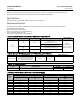
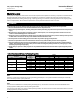
Instruction Manual EH (1-1/2x1 through 8x6) D100394X012 December 2014 Table 1. Specifications End Connection Styles Buttwelding: All available ASME B16.25 schedules that are compatible with ASME B16.34 pressure/temperature ratings Flanged: CL2500 J ring-type joint (RTJ) or J raised-face (RF) flanges according to ASME B16.5 Socket Welding: Consistent with ASME B16.11 Maximum Inlet Pressure(1) Buttwelding: Consistent with CL2500 pressure-temperature ratings per ASME B16.
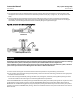
Instruction Manual EH (1-1/2x1 through 8x6) D100394X012 December 2014 applied in processes with a fluid temperature of up to 593_C (1100_F), provided other material limits are not exceeded. Contact your Emerson Process Management sales office for information. Specifications Specifications for the EHD, EHS, and EHT valves are shown in table 1.
EH (1-1/2x1 through 8x6) December 2014 Instruction Manual D100394X012 Installation WARNING Always wear protective gloves, clothing, and eyewear when performing any installation operations to avoid personal injury. To avoid personal injury or property damage resulting from the sudden release of pressure, do not install the valve assembly where service conditions could exceed the limits given in this manual or on the appropriate nameplates.
Instruction Manual EH (1-1/2x1 through 8x6) D100394X012 December 2014 3. The control valve must be installed with the actuator vertical above the valve body for proper operation. Flow through the valve must be in the direction indicated by the flow arrow (key 15, figure 17, 18, or 20) on the valve body. 4. Use accepted piping and welding practices when installing the valve in the line.
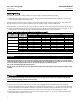
Instruction Manual EH (1-1/2x1 through 8x6) D100394X012 December 2014 Maintenance Valve parts are subject to normal wear and must be inspected and replaced as necessary. Inspection and maintenance frequency depends on the severity of service conditions. This section includes instructions for packing lubrication, packing maintenance, adding packing rings, replacing packing, trim removal, valve plug maintenance, lapping seats, and trim replacement.
Instruction Manual D100394X012 EH (1-1/2x1 through 8x6) December 2014 WARNING Personal injury could result from packing leakage. Valve packing was tightened prior to shipment; however some readjustment will be required to meet specific service conditions. Check with your process or safety engineer for any additional measures that must be taken to protect against process media. Packing Lubrication CAUTION Do not lubricate graphite packing. Graphite packing is self-lubricated.
Instruction Manual EH (1-1/2x1 through 8x6) D100394X012 December 2014 Replacing Packing Key numbers referred to in this procedure are shown in figure 16 unless otherwise indicated. 1. Isolate the control valve from the line pressure, release pressure from both sides of the valve body, and drain the process media from both sides of the valve. Remove the cap screws in the stem connector, and separate the two halves of the stem connector.
Instruction Manual EH (1-1/2x1 through 8x6) D100394X012 December 2014 Figure 3.
Instruction Manual EH (1-1/2x1 through 8x6) D100394X012 December 2014 Figure 4.
Instruction Manual D100394X012 EH (1-1/2x1 through 8x6) December 2014 rounded rod or other tool that will not scratch the packing box wall. For extension bonnets, also remove the baffle (key 2) and retaining ring (key 35). 9. Clean the packing box and the following metal packing parts: packing follower (key 13), packing box ring (key 11), spring or lantern ring (key 8, figures 4 and 16), and, for single arrangements of PTFE V-ring packing only, special washer (key 10, figures 4 and 16). 10.
Instruction Manual EH (1-1/2x1 through 8x6) D100394X012 December 2014 When all nuts are tightened to that torque value, increase the torque by one fourth of the specified nominal torque and repeat the crisscross pattern. Repeat this procedure until all nuts are tightened to the specified nominal value. Apply the final torque value again and, if any nut still turns, tighten every nut again. Figure 5.
Instruction Manual EH (1-1/2x1 through 8x6) D100394X012 December 2014 If desired, a tool can also be machined for a valve of specific size and valve class using the dimensions shown in figure 9. Machine the tool from a material listed in figure 9 or from a material with a yield strength of at least 827 MPa (120,000 psi). Using a tool of lower strength material may result in damage to the seat ring retainer or valve body threads.
Instruction Manual EH (1-1/2x1 through 8x6) D100394X012 December 2014 Figure 6. Detail of Protected Soft Seat OUTER PLUG INNER PLUG CAGE PROTECTED SOFT SEAT SEAT RING A7088 TSO Trim Refer to figure 7. 1. Remove the retainer, backup ring, anti-extrusion rings, and piston ring. 2. Remove the set screws that lock the outer plug to the inner plug. 3. Using a strap wrench or similar tool, unscrew the outer plug from the inner plug. Do not damage the outer plug guide surfaces. 4.
Instruction Manual EH (1-1/2x1 through 8x6) D100394X012 December 2014 Figure 7. Typical Balanced TSO Trim VALVE PLUG SEAL A7096 PROTECTED SOFT SEAT Valve Plug Maintenance Key numbers used in this procedure are shown in figure 17 for the EHD valve, in figure 18 for the EHS valve, and in figure 20 for the EHT valve. 1.
EH (1-1/2x1 through 8x6) December 2014 Instruction Manual D100394X012 3. Thread the new stem into the valve plug and tighten it to the appropriate torque value given in table 10. Using the valve plug pin hole as a guide, drill the pin hole through the stem. Refer to table 10 for drill sizes. 4. Drive in the pin to lock the assembly. 5. If it is necessary to lap the seating surfaces, complete the Lapping Seats procedure before installing the EHD piston rings or the EHT seal ring.
Instruction Manual EH (1-1/2x1 through 8x6) D100394X012 December 2014 Figure 8. Trim Surfaces Requiring Lubrication SEAT RING RETAINER 1 1 SEAT RING GASKET OR O-RING SEAT RING VALVE BODY A3583 1 LUBRICATION REQUIRED CAUTION Thoroughly clean the seat ring (key 6), seat ring retainer (key 7), and the retainer threads in the valve body with a good-quality degreaser. Also clean all cage gasket surfaces.
Instruction Manual EH (1-1/2x1 through 8x6) D100394X012 December 2014 TOOL DIMENSIONS VALVE SIZE, NPS/ RATING mm A B Inches C D(1) 111.3 11.2 E F H J(1) 7.9 11.2 12.4 12.2 19.1 2.00 G K C D(1) 1.25 1.34 1.827 1.807 4.38 0.44 A B E F H J(1) K 0.31 0.44 0.49 0.48 0.75 G 1-1/2 x1/ CL2500 50.8 31.8 34.1 46.4 45.9 2x1/ CL2500 50.8 31.8 34.1 46.4 45.9 111.3 11.2 7.9 11.2 12.4 12.2 19.1 2.00 1.25 1.34 1.827 1.807 4.38 0.44 0.31 0.44 0.49 0.48 0.
Instruction Manual EH (1-1/2x1 through 8x6) D100394X012 December 2014 Table 9.
EH (1-1/2x1 through 8x6) December 2014 Instruction Manual D100394X012 CAUTION Hold the torque wrench at right angles to the seat ring retainer when applying torque. Tilting the tool and extension while applying torque may cause the lugs on the seat ring retainer tool to suddenly disengage from the recesses in the retainer, damaging the retainer and seat ring. e. Tighten the seat ring retainer to the torque shown in table 9. Note Some cages have one large window and several small windows.
Instruction Manual D100394X012 EH (1-1/2x1 through 8x6) December 2014 Secure with the retaining ring (key 10). For an NPS 6 valve with a level D Whisper Trim III cage, reinstall the piston ring (key 30) following the instructions given in the paragraph immediately preceding. 2. Install the valve plug into the cage. TSO Trim Refer to figure 7. 1.
Instruction Manual EH (1-1/2x1 through 8x6) D100394X012 December 2014 serial card provided with this product. Use of unapproved materials and parts could lead to stresses exceeding the design or code limits intended for this particular service. Install studs with the material grade and manufacturer's identification mark visible. Contact your Emerson Process Management representative immediately if a discrepancy between actual parts and approved parts is suspected. 3.
Instruction Manual EH (1-1/2x1 through 8x6) D100394X012 December 2014 CAUTION To avoid leakage when the valve is returned to service, use appropriate methods and materials to protect all sealing surfaces of the new trim parts while assembling the individual parts and during installation in the valve body. 1. Apply a suitable high-temperature lubricant to the inside diameter of the C-seal plug seal.
Instruction Manual EH (1-1/2x1 through 8x6) D100394X012 December 2014 FOR VALVE PLUGS FITTING PORT SIZE (Inches) DIMENSIONS, mm (See Drawing Below) Part Number (To Order A Tool) A B C D E F G H 2.875 82.55 52.324 52.578 4.978 - 5.029 3.708 - 3.759 41.148 52.680 52.781 55.118 55.626 70.891 - 71.044 24B9816X012 3.4375 101.6 58.674 58.928 4.978 - 5.029 3.708 - 3.759 50.8 61.011 61.112 63.449 63.957 85.166 - 85.319 24B5612X012 3.625 104.394 65.024 65.278 4.978 - 5.029 3.
Instruction Manual EH (1-1/2x1 through 8x6) D100394X012 December 2014 CAUTION To avoid excessive leakage and seat erosion, the valve plug must be initially seated with sufficient force to overcome the resistance of the C-seal plug seal and contact the seat ring. You can correctly seat the valve plug by using the same force calculated for full load when sizing your actuator.
Instruction Manual EH (1-1/2x1 through 8x6) D100394X012 December 2014 Figure 12. Installing the C-seal Plug Seal Using the Installation Tool INSTALLATION TOOL C-seal METAL PLUG SEAL VALVE PLUG HORIZONTAL REFERENCE SURFACE FLOW DOWN NOTE: PRESS INSTALLATION TOOL OVER VALVE PLUG UNTIL THE TOOL CONTACTS THE HORIZONTAL REFERENCE SURFACE OF THE VALVE PLUG. A6778 Figure 13.
Instruction Manual EH (1-1/2x1 through 8x6) D100394X012 December 2014 seal contacts the cage, and inspect the sealing surface where the C-seal plug seal makes contact with the plug (figure 14). 9. Replace or repair trim parts according to the following procedure for lapping metal seats, remachining metal seats, or other valve plug maintenance procedures as appropriate.
Instruction Manual EH (1-1/2x1 through 8x6) D100394X012 December 2014 3. Place the C-seal plug seal over the top of the valve plug and press it onto the plug using the installation tool. Carefully press the C-seal plug seal onto the plug until the installation tool contacts the horizontal reference surface of the valve plug (figure 12). 4. Apply a suitable high-temperature lubricant to the threads on the plug.
Instruction Manual EH (1-1/2x1 through 8x6) D100394X012 December 2014 Parts Ordering Each body-bonnet assembly is assigned a serial number, which can be found on the valve body. This same number also appears on the actuator nameplate when the valve body is shipped from the factory as part of a control valve assembly. Refer to the number when contacting your Emerson Process Management sales office for technical assistance or when ordering replacement parts.
Instruction Manual EH (1-1/2x1 through 8x6) D100394X012 December 2014 Parts List Note Part numbers are shown for recommended spares only. For part numbers not shown, contact your Emerson Process Management sales office.
Instruction Manual EH (1-1/2x1 through 8x6) D100394X012 December 2014 Figure 16.
Instruction Manual EH (1-1/2x1 through 8x6) D100394X012 December 2014 Figure 17.
Instruction Manual EH (1-1/2x1 through 8x6) D100394X012 December 2014 Figure 18.
Instruction Manual EH (1-1/2x1 through 8x6) D100394X012 December 2014 Figure 19.
Instruction Manual EH (1-1/2x1 through 8x6) D100394X012 December 2014 Figure 20.
Instruction Manual EH (1-1/2x1 through 8x6) D100394X012 December 2014 Figure 21.
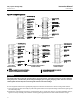
Instruction Manual EH (1-1/2x1 through 8x6) D100394X012 December 2014 Keys 6*, 7*, and 12* Soft Packing Parts PACKING ARRANGEMENT KEY NUMBER PACKING PART DESCRIPTION PTFE V-Ring Packing 6 12 Low chloride graphite ribbon and filament, single 6 7 7 Low chloride graphite ribbon and filament, double 6 7 7 PTFE/ composition, double 6 7 12 VALVE STEM CONNECTION 12.7 mm (1/2 Inch) 19.1 mm (3/4 Inch) 25.4 mm (1-Inch) 31.
Instruction Manual EH (1-1/2x1 through 8x6) D100394X012 December 2014 Keys 8, 10, 11* and 13 Metal Packing Parts PACKING TYPE PTFE V-Ring Low Chloride Graphite Ribbon/Filament PTFE/Composition 38 QUANTITY REQUIRED KEY NUMBER DESCRIPTION 8 VALVE STEM CONNECTION MATERIAL Single Packing Double Packing mm Inches 316 Stainless Steel Packing Spring 1 1 1 1 --------- 12.7 19.1 25.4 31.
Instruction Manual EH (1-1/2x1 through 8x6) D100394X012 December 2014 Key 2* Cage For Valve Bodies Without Whisper Trim III Cage or Cavitrol III Trim VALVE BODY RATING VALVE SIZE, NPS CAGE DESCRIPTION 1-1/2 x 1, 2x1 3x2 CL2500 3, 4 x 3 4, 6 x 4 6, 8 x 6(2) TRAVEL MATERIAL S17400 (17-4PH Stainless Steel) with H1075 Heat Treatment S42200 (422 Stainless Steel) Ion Nitride S31600 (316 Stainless Steel) Electrolized S31600 (316 Stainless Steel) Electroless Nickel Coated for NACE MR0175-2002(1) mm I
Instruction Manual EH (1-1/2x1 through 8x6) D100394X012 December 2014 C-seal Parts for Fisher EHD Valve (Keys 2*, 3*, 6*, 64*, 8*, and 4*) VALVE SIZE PORT DIA TRAVEL NPS Inch Inch 4 CL2500 2.875 2 TRIM 54 STEM DIAMETER mm Inch 19.
Instruction Manual EH (1-1/2x1 through 8x6) D100394X012 December 2014 Key 3* Valve Plug for 1-1/2 x 1 and 2 x 1 Fisher EHS Valve Body with Micro-Flute Valve Plug MATERIAL PORT DIAMETER VALVE BODY RATING PLUG STYLE CL2500 1 Flute 2 Flutes 3 Flutes 3 Flutes 3 Flutes S31600 (316 Stainless Steel) With CoCr-A (Alloy 6) Seat, Guide, and Tip mm Inches Diameter B(1) 6.4 6.4 6.4 9.5 12.7 0.25 0.25 0.25 0.375 0.
Instruction Manual EH (1-1/2x1 through 8x6) D100394X012 December 2014 Key 3* Valve Plug or Plug/Diverter for an NPS 6 CL2500 Valve Without Micro-Form, Micro-Flute, or Cavitrol III Trim VALVE SIZE, NPS VALVE BODY DESIGN EHD EHD with diverter( 4) 6, 8 x 6 EHT EHT with diverter( 4) EHS 1. 2. 3. 4. MATERIAL VALVE STEM CONNECTION S31600 (316 Stainless Steel) With CoCr-A (Alloy 6) Seat and Guide mm Inches mm Inches S31600 (316 Stainless Steel) With CoCr-A (Alloy 6) Seat and Guide 19.1 25.4 31.
Instruction Manual EH (1-1/2x1 through 8x6) D100394X012 December 2014 Key 3* Valve Plug for NPS 6 and 8 x 6 Valve with Whisper Trim III Cage VALVE BODY DESIGN MATERIAL 17-4PH stainless steel with H900 heat treatment(1) _C _F DIAMETER CODE STAMPED ON TOP OF VALVE PLUG 0 to 427 32 to 800 N.A.
Instruction Manual EH (1-1/2x1 through 8x6) D100394X012 December 2014 Key 4* Valve Plug Stem for CL2500 Valve without Whisper Trim III or Cavitrol III Trim VALVE SIZE, NPS ACTUATOR GROUP VALVE STEM CONNECTION mm 12.7 1-1/2 x 1, 2x1 Inches 1/2 100 101 S31600 (316 Stainless Steel) Electrolized S31600 S20910 for NACE MR0175-2002 Micro-Form or MicroFlute with 6.4 mm (0.25-inch) port 10A8840XB42 13A7368X062 10A8840XT82 0.75 Micro-Flute with 9.5 mm (0.375-inch) or 12.7 mm (0.
Instruction Manual EH (1-1/2x1 through 8x6) D100394X012 December 2014 Key 4* Valve Plug Stem for NPS 4 or 6 Valve with Whisper Trim III Cage VALVE BODY RATING, CLASS VALVE SIZE, NPS ACTUATOR GROUP 4, 6 x 4 2500 6, 8 x 6 VALVE STEM CONNECTION VALVE STEM TRAVEL MATERIAL mm Inches mm Inches 1 19.1 3/4 51 2 EHD, EHT EHS All All S17400 (17-4PH Stainless Steel) with H1150 Heat Treatment ----- 100 25.
Instruction Manual EH (1-1/2x1 through 8x6) D100394X012 December 2014 Key 6* Seat Ring and Key 7* Seat Ring Retainer for Gasketed Seat Ring Constructions without Cavitrol III or NPS 4 or 6 Whisper Trim III Cage VALVE BODY RATING, CLASS VALVE SIZE, NPS SEAT RING MATERIAL PORT DIAMETER DESIGN PART DESCRIPTION mm Inches 6.4 0.25 9.5 0.375 12.7 0.5 19.1 0.75 Micro-Form 25.4 1 EHD, EHT, EHS 38.1 1.5 3, 4 x 3 EHD, EHT, EHS 58.7 2.3125 4, 6 x 4 EHD, EHT, EHS 73.0 2.
Instruction Manual EH (1-1/2x1 through 8x6) D100394X012 December 2014 Key 6* Seat Ring and Key 7* Seat Ring Retainer for a NPS 4 or 6 Valve with Whisper Trim III Cage and Gasketed Seat Ring Construction VALVE BODY RATING, CLASS SEAT RING MATERIAL PORT DIAMETER VALVE SIZE, NPS mm Inches 4, 6 x 4 73.0 2.875 6, 8 x 6 111.1 4.
Instruction Manual EH (1-1/2x1 through 8x6) D100394X012 December 2014 Key 8* R30003/PTFE Seal Ring and Key 30* Graphite Piston Ring for Fisher EHT without Cavitrol III Trim KEY 8 SEAL RING PORT DIAMETER VALVE SIZE, NPS KEY 30 PISTON RING Valve Body Rating mm Inches CL2500 3x2 38.1 47.6 1.5 1.875 13A8521X032 --- N.A. 3, 4 x 3 58.7 2.3125 10A4206X032 N.A. 4, 6 x 4 73.0 2.875 10A4215X032 N.A. 6, 8 x 6 without Whisper Trim III 111.1 4.375 10A4223X032 N.A.
Instruction Manual EH (1-1/2x1 through 8x6) D100394X012 December 2014 Figure 22.
Instruction Manual EH (1-1/2x1 through 8x6) D100394X012 December 2014 TSO Parts for Fisher EHS and EHT Valves (Keys 2*, 6*, and 3*) VALVE SIZE CLASS NPS PORT DIA TVL Inch Inch TRIM mm 810 816 6 EHT 2500 4.1875 3.75 STEM DIAMETER 19.1 Inch 3/4 810 25.
Instruction Manual EH (1-1/2x1 through 8x6) D100394X012 December 2014 TSO Parts for Fisher EHS and EHT Valves (Keys 8*, 63*, 9*, and 10*) VALVE SIZE CLASS NPS PORT DIA TVL Inch Inch TRIM mm 810 816 6 EHT 2500 4.1875 3.75 STEM DIAMETER 19.1 Inch 3/4 810 25.
Instruction Manual EH (1-1/2x1 through 8x6) D100394X012 December 2014 Actuator Groups by Type Number Group 1 54 mm (2-1/8 Inch), 71 mm (2-13/16 Inch), or 90 mm (3-9/16 Inch) Yoke Boss 472 & 473 585C, 585CR (50.8 mm [2 inch] maximum travel) 1B & 655 657 & 667–76.2 mm (3 Inch) maximum travel 657-4, 667-4 (76.2 mm [3 inch] travel) 1008–Except 90 mm (3-9/16 Inch) yoke boss with 50.8 mm (2 inch) travel 3024C, 3025 685SE, 685SR (76.