
Data Sheet

GX 3--Way Valve and Actuator
Product Bulletin
51.1:GX 3--Way
August 2011
15
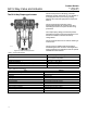
Actuator Selection
With the GX 3-Way, actuator selection has never
been easier. Once the valve size has been
determined, the actuator is automatically selected.
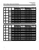
The following tables provide the maximum allowable
pressure drops for the GX 3-Way.Seetable8for
Side Port Common construction and table 9 for
Bottom Port Common construction. For optimal
performance, the GX 3-Way should be operated with
a FIELDVUE digital valve controller.
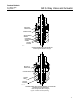
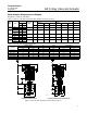
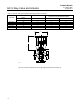
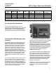
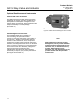
GX ISO 5210 Electric Actuator
Mounting
Electric actuator mounting is available for any
manufacturing models that comply with ISO 5210,
Flange type F7. The mounting o ffering includes a
GX yoke, actuator rod adaptor, spacer, and bolting.
Thrust limitations apply when sizing electric
actuators ( see table 7).
Mounting offering can be engineered if not already
available for a selected a ctuator. For additional
information, contact your Emerson Process
Management sales office.
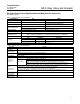
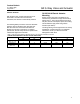
Table 7. Fisher GX 3--Way Maximum Allowable Thrust for use with ISO 5210 Electric Actuators
(THRUST LIMITATIONS APPLY IN BOTH TRAVEL DIRECTIONS)
VALVE SIZE
STEM DIAMETER TRAVEL
STEM MATERIAL
MAXIMUM THRUST
mm mm N lbf
DN25--DN40
(NPS1to1--1/2)
10 19 S31603 6900 1550
DN50 (NPS 2) 14 19 S31603 14000 3150
DN80--DN100
(NPS3to4)
14 38 S31603 14000 3150