
Data Sheet
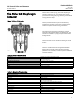


GX Control Valve and Actuator
D103171X012
Product Bulletin
51.1:GX
March 2012
16
Actuator Selection
With the GX, actuator selection has never been easier.
Once the valve size and port diameter have been
determined, the actuator is automatically selected. No
spring selection or bench set calculations are required.
The majority of GX constructions (both fail-down and
fail-up) are rated to a full pressure class shutoff
capability of 51.7 bar (750 psi) for a 4 to 6 bar (58 to 87
psig) actuator air supply. Refer to Fisher bulletin
51.1:GX (S1) for additional information.
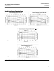
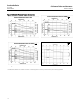
The GX actuator has been optimized to allow for
varying ranges of supply pressure. See table 12.
Table 12. Fisher GX Actuator Supply Pressure Ranges
SUPPLY PRESSURE
RANGE
Bar Psig
Standard 4.0 to 6.0 58 to 87
Optional 3.0 to 4.0 44 to 58
Optional 2.0 to 3.0 29 to 44
GX ISO 5210 Electric
Actuator Mounting
Electric actuator mounting is available for any
manufacturing models that comply with ISO 5210,
Flange type F7. The mounting offering includes a GX
yoke, actuator rod adaptor, spacer, and bolting.
CAUTION
The up travel stop must be set in the electric actuator in
order to prevent damage to the valve trim.
Thrust limitations apply when sizing electric actuators
(see table 13).
Mounting offering can be engineered if not already
available for a selected actuator. Electric actuator
mounting is not available for DN150, NPS 6 GX valves.
For additional information, contact your Emerson
Process Management sales office.
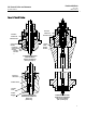
Bellows Extension Bonnet
The GX bellows extension bonnet provides reliable and
tight stem sealing for those applications where
emissions escaping to the environment cannot be
tolerated (see figure 15). The GX bellows is available in
SST (1.4571 / 316Ti) or N10276 and covers a full range
of valve sizes from DN 15 through DN 100 (NPS 1/2
through4)(seetables14and15).
The GX bellows system has been designed for 100,000
full-travel cycles at maximum allowable pressure and
ambient temperature (20_C[68_F]).
The mechanically-formed metal bellows provides high
operating reliability and extended cycle life (see tables
16, 17, and 18 for details).
The GX bellows design incorporates a rugged double-
or triple-wall construction for added security. Each
bellows has been tested with helium before it leaves
the factory.
The GX bellows bonnet comes standard with a
live-loaded, PTFE packing system as a security backup.
A connection is provided above the bellows to allow
purging or monitoring the integrity of the replaceable
bellows.
Table 13. Fisher GX Maximum Allowable Thrust for use with ISO 5210 Electric Actuators
VALVE SIZE
STEM DIAMETER TRAVEL
BONNET STYLE
STEM MATERIAL
STRENGTH
MAXIMUM THRUST
mm mm N lbf
DN15-DN50
(NPS 1/2 to 2)
10 20
Plain
High
(1)
17000 3820
Low
(2)
7600 1710
Bellows/Extension
High 11400 2560
Low 6700 1500
DN80-DN100
(NPS 3 to 4)
14 20, 40
Plain
High 20000 4500
Low 20000 4500
Bellows/Extension
High 20000 4500
Low 14500 3260
1. High strength stem materials consist of S20910, N05500, S31603
2. Low strength stem materials consist of S31803, N10665, N06022