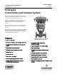
Product Bulletin GX Control Valve and Actuator 51.1:GX March 2012 D103171X012 Fisherr GX Control Valve and Actuator System The Fisher GX is a compact, state-of-the-art control valve and actuator system, designed to control a wide range of process liquids, gases, and vapors. The GX is rugged, reliable, and easy to select. It requires no actuator sizing -- the actuator selection is automatic once the valve body construction is selected. The optimized design results in reduced complexity and parts count.
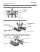
Product Bulletin GX Control Valve and Actuator 51.1:GX March 2012 D103171X012 Figure 1. Fisher GX Control Valve Assembly with Port-Guided Contoured Plug (Port Sizes 36 to 136 mm) COMPACT FIELD-REVERSIBLE MULTI-SPRING ACTUATOR INTEGRAL PNEUMATIC PASSAGEWAYS INTEGRATED POSITIONER MOUNTING NAMUR POSITIONER MOUNTING CAPABILITY ONE-PIECE SCREWED PACKING FOLLOWER STANDARD LIVE-LOADED PACKING CLAMPED BONNET DESIGN W8568-1A Optimized valve and actuator system.
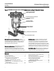
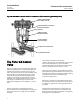
Product Bulletin GX Control Valve and Actuator 51.1:GX March 2012 D103171X012 Figure 2. Fisher GX and DVC2000 Digital Valve Controller Figure 3. Fisher GX Cryogenic Valve LINKAGE-LESS POSITION FEEDBACK DVC2000 COVER W8588 PUSH-BUTTON INSTRUMENT SETUP Stable flow control. The flow cavity of the GX valve body has been engineered to provide stable flow and reduce process variability. Live-loaded packing. The GX comes with live-loaded PTFE V-ring packing as standard.
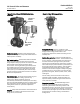
Product Bulletin GX Control Valve and Actuator 51.1:GX March 2012 D103171X012 Figure 4. Fisher GX Principle of Operation -- Actuator Air Supply AIR SUPPLY AIR VENT AIR VENT AIR SUPPLY FAIL-DOWN The DVC2000 mounting interface is identical on both sides of the actuator yoke for valve body sizes DN 15 through DN 100 (NPS 1/2 through 4). This symmetrical design allows the DVC2000 to be easily moved from one side of the valve to the other without the need to rotate the actuator.
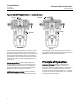
Product Bulletin GX Control Valve and Actuator 51.1:GX March 2012 D103171X012 Figure 5. Fisher GX Control Valve with Typical Soft Seat Trim Construction (Port Sizes of 22 - 136mm) PTFE SEAT SCREWED-IN SEAT RING W9023-1 PLUG Figure 6.
Product Bulletin GX Control Valve and Actuator 51.1:GX March 2012 D103171X012 Figure 8.
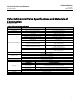
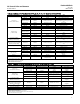
Product Bulletin GX Control Valve and Actuator 51.1:GX March 2012 D103171X012 Fisher GX Control Valve Specifications and Materials of Construction See tables 1 and 2. Table 1. Fisher GX Valve Specifications Specifications EN ASME Valve Body Size DN 15, 20, 25, 40, 50, 80, 100, 150 NPS 1/2, 3/4, 1, 1-1/2, 2, 3, 4, 6 Pressure Rating PN 10 / 16 / 25 / 40 per EN 1092-1 CL150 / 300 per ASME B16.34 End Connections Flanged raised face per EN 1092-1 Flanged raised face per ASME B16.
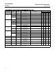
Product Bulletin GX Control Valve and Actuator 51.1:GX March 2012 D103171X012 Table 2.
Product Bulletin GX Control Valve and Actuator 51.1:GX March 2012 D103171X012 Table 5.
Product Bulletin GX Control Valve and Actuator 51.1:GX March 2012 D103171X012 Table 7. Allowable Temperature Ranges for Valve Body, Bonnet and Trim(1) VALVE BODY / BONNET MATERIAL 1.0619/SA216 WCC Steel PACKING Standard PTFE or Graphite ULF Extension Bellows 1.
Product Bulletin GX Control Valve and Actuator 51.1:GX March 2012 D103171X012 Figure 9. Material Pressure/Temperature Curves 1 E1026 E1140 1. N7M is only offered with CL150 and CL300 (not PN10, PN16, PN25, or PN40).
Product Bulletin GX Control Valve and Actuator 51.1:GX March 2012 D103171X012 Figure 10. Material Pressure/Temperature Curves 1 1 E0901 1. CD3MN, CN7M, and M35-2 are not listed in EN 12516-1. The PN designations are used only to indicate relative pressure-retaining capabilities.
Product Bulletin GX Control Valve and Actuator 51.1:GX March 2012 D103171X012 Figure 11.
Product Bulletin GX Control Valve and Actuator 51.1:GX March 2012 D103171X012 Figure 12. GX Cavitrol III Trim Figure 13. GX Whisper Trim III GX Cavitrol III for DN25 (NPS 1) through DN50 (NPS 2) Cavitrol III trim lowers hydrodynamic noise and reduces vibration by utilizing proprietary drilled hole shape and spacing to shift the frequency and isolate the cavitation in order to prevent damage. Cavitrol III 1stage technology is used without altering the integral GX bonnet design.
Product Bulletin GX Control Valve and Actuator 51.1:GX March 2012 D103171X012 The Fisher GX Diaphragm Actuator The GX uses a multi-spring, pneumatic diaphragm actuator (see figure 14). It is capable of air supply pressures to 6.0 barg (87 psig), allowing valve shutoff at high pressure drops. Figure 14. Fisher GX Actuator The GX product selection system automatically matches the actuator to the valve, eliminating the need for complex actuator sizing procedures.
Product Bulletin GX Control Valve and Actuator 51.1:GX March 2012 D103171X012 Actuator Selection Thrust limitations apply when sizing electric actuators (see table 13). With the GX, actuator selection has never been easier. Once the valve size and port diameter have been determined, the actuator is automatically selected. No spring selection or bench set calculations are required. Mounting offering can be engineered if not already available for a selected actuator.
Product Bulletin GX Control Valve and Actuator 51.1:GX March 2012 D103171X012 Figure 15. Fisher GX Bellows Bonnet and Selection Process Bellows Selection Process PACKING FOLLOWER BONNET LIVE-LOADED PTFE PACKING PURGE / MONITORING CONNECTION Follow this process to assist in selecting the appropriate bellows for the application. Step 1 Size and select the GX control valve that is appropriate for the application.
Product Bulletin GX Control Valve and Actuator 51.1:GX March 2012 D103171X012 Table 14. Fisher GX Constructions with Bellows Availability VALVE BODY SIZES PORT SIZE (mm) ACTUATOR SIZES PLUG TRAVEL TRIM STYLE DN15-50 (NPS 1/2 to 2) 4.8 to 46 225 and 750 20 mm Unbalanced DN80 (NPS 3) 36 to 46 750 20 mm Unbalanced 70 750 20 mm Balanced DN100 (NPS 4) 46 750 20 mm Unbalanced 90 750 20 mm Balanced Table 15. Bellows Materials of Construction Valve Body / Bonnet Carbon Steel (1.
Product Bulletin GX Control Valve and Actuator 51.1:GX March 2012 D103171X012 Cycle Life Bellows service life is affected by several factors, including process pressure, temperature, and plug travel. Tables 16, 17, 18, and 19 provide estimates of cycle life for several cases. Table 16. Estimated Bellows Cycle Life at 10.
Product Bulletin GX Control Valve and Actuator 51.1:GX March 2012 D103171X012 Bellows Pressure - Temperature Ratings See figure 16. Figure 16. Bellows Pressure - Temperature Ratings Pressure-Temperature Ratings for 1.
Product Bulletin GX Control Valve and Actuator 51.1:GX March 2012 D103171X012 Valve-Actuator Dimensions and Weights See figure 17 and table 20. Figure 17. Fisher GX Dimensions (also see table 20) AR E D F C A/2 W8486-3 A GX STEM-GUIDED CONSTRUCTION (DN25 / NPS 1) Table 20.
Product Bulletin GX Control Valve and Actuator 51.1:GX March 2012 D103171X012 Figure 18. Fisher GX Electric Actuator Mounting Dimensions (also see table 21) H G GE54731-1 GX ELECTRIC ACTUATOR MOUNTING Table 21. Fisher GX Electric Actuator Mounting Dimensions and Weights GX ELECTRIC ACTUATOR MOUNTING WEIGHT PORT DIAMETER G H mm mm mm With Standard Bonnet kg DN 15/ NPS 1/2 4.8, 9.5 202 176 12 16 DN 20/ NPS 3/4 4.8, 9.5, 14 202 176 13 17 DN 25/ NPS 1 4.8, 9.
Product Bulletin GX Control Valve and Actuator 51.1:GX March 2012 D103171X012 Table 22. Positioner Selection Guidelines Digital I/P(1) DVC2000 X X DVC6200 X X 3661 I/P(2) P/P(3) Intrinsic Safety(4) Type X 3660 Flameproof / Explosionproof(4) Non- Incendive(4) X X X X X X 1. Digital I/P - microprocessor based electro-pneumatic with HART communication. 2. I/P - electro-pneumatic 3. P/P - pneumatic 4. Refer to Fisher bulletin 9.2:001 for instrument hazardous area classification details.
Product Bulletin GX Control Valve and Actuator 51.1:GX March 2012 Optional Positioners and Instruments D103171X012 Figure 20. Fisher GX Valve with 3660 or 3661 Posi tioner, NAMUR Mounting (IEC 60534-6-1) Fisher 3660 and 3661 Valve Positioners The 3660 pneumatic and 3661 electro-pneumatic positioners are rugged, accurate, and feature low steady-state air consumption. Designed to meet intrinsic safety requirements, these positioners offer simple functionality in a small package.
Product Bulletin GX Control Valve and Actuator 51.1:GX March 2012 D103171X012 Manual Handwheels actuators. Dimensions are provided in figure 23 and table 23. The GX is available with an optional, side-mounted manual handwheel (see figure 22). These handwheels provide a robust method of manually operating the valve in an emergency or upon loss of instrument air. When mounted to a fail-up actuator, rotating the handwheel clockwise moves the stem downwards.
Product Bulletin GX Control Valve and Actuator 51.1:GX March 2012 D103171X012 Figure 23. Fisher GX with Handwheel Dimensions (also see table 23) B C1 B C2 A1 A2 A1 A2 E0975 Table 23. Fisher GX with Handwheel Dimensions and Weights VALVE SIZE EN NPS ACTUATOR SIZE VALVE TRAVEL HANDWHEEL WEIGHT A1 A2 B C1(1) C2(2) mm kg mm mm mm mm mm DN 15 1/2 225 20 5.6 215 242 223 159 60 DN 20 3/4 225 20 5.6 215 242 223 159 60 DN 25 1 225 20 5.
Product Bulletin GX Control Valve and Actuator 51.1:GX March 2012 D103171X012 Coefficients Table 24. Fisher GX, Equal Percentage Valve Plug, Flow Up Through the Port Equal Percentage Characteristic Equal Percentage - Flow Up Valve Size Port Maximum Diameter Travel mm mm 9.5 20 DN 15 (NPS 1/2) 9.5(2) 14 DN 20 (NPS 3/4) 9.5 9.5(2) 20 20 20 20 Flow Coefficient 10 20 30 40 50 60 70 80 90 100 Cv 0.118 0.191 0.309 0.457 0.607 0.941 1.39 2.00 2.77 3.34 0.98 Kv 0.102 0.
Product Bulletin GX Control Valve and Actuator 51.1:GX March 2012 D103171X012 Table 24. Fisher GX, Equal Percentage Valve Plug, Flow Up Through the Port (continued) Equal Percentage Characteristic Equal Percentage - Flow Up Valve Size Port Maximum Diameter Travel mm mm 22 14 20 20 DN 25 (NPS 1) 9.5 9.5(2) 36 DN 40 (NPS 1-1/2) 22 14 46 DN 50 (NPS 2) 36 22 20 20 20 20 20 20 20 20 Flow Coefficient 10 20 30 40 50 60 70 80 90 100 Cv 0.673 0.937 1.32 1.89 2.25 3.
Product Bulletin GX Control Valve and Actuator 51.1:GX March 2012 D103171X012 Table 24. Fisher GX, Equal Percentage Valve Plug, Flow Up Through the Port (continued) Equal Percentage Characteristic Equal Percentage - Flow Up Valve Size Port Maximum Diameter Travel mm mm 70 70(3) 40 20 DN 80 (NPS 3) 46 36 90 90(3) DN 100 (NPS 4) 90(4) 70 46 20 20 40 20 20 40 20 Flow Coefficient 10 20 30 40 50 60 70 80 90 100 Cv 2.38 6.92 11.5 16.4 22.4 31.9 46.5 63.6 80.6 95.
Product Bulletin GX Control Valve and Actuator 51.1:GX March 2012 D103171X012 Table 24. Fisher GX, Equal Percentage Valve Plug, Flow Up Through the Port (continued) Equal Percentage Characteristic Equal Percentage - Flow Up Valve Size Port Maximum Diameter Travel mm mm 136 DN 150 (NPS 6) 136(3) 90(2) 1. At 100% travel. 2. Restricted trim. 3. Balanced trim. 4. Balanced, restricted trim. 30 60 60 40 Flow Coefficient 10 20 30 40 50 60 70 80 90 100 Cv 13.8 25.0 40.0 60.0 90.
Product Bulletin GX Control Valve and Actuator 51.1:GX March 2012 D103171X012 Table 25. Fisher GX, Linear Valve Plug, Flow Up Through the Port Linear Characteristic Linear - Flow Up Valve Size Port Maximum Diameter Travel mm mm 9.5 4.8(4) 9_30' DN 15 (NPS 1/2) 4.8(4) 4_39' 4.8(4) 2_15' 4.8(4) 1_8' 14 9.5 4.8(4) 9_30' DN 20 (NPS 3/4) 4.8(4) 4_39' 4.8(4) 2_15' 4.8(4) 1_8' 20 20 20 20 20 20 20 20 20 20 20 Flow Coefficient 10 20 30 Cv 0.179 0.415 Kv 0.155 0.359 XT 0.
Product Bulletin GX Control Valve and Actuator 51.1:GX March 2012 D103171X012 Table 25. Fisher GX, Linear Valve Plug, Flow Up Through the Port (continued) Linear Characteristic Linear - Flow Up Valve Size Port Maximum Diameter Travel mm mm 22 14 9.5 DN 25 (NPS 1) 4.8(4) 9_30' 4.8(4) 4_39' 4.8(4) 2_15' 4.8(4) 1_8' 36 DN 40 (NPS 1-1/2) 22 14 20 20 20 20 20 20 20 20 20 20 Flow Coefficient 10 20 30 40 50 60 70 80 90 100 Cv 1.72 3.06 4.50 7.04 8.52 9.74 11.1 12.
Product Bulletin GX Control Valve and Actuator 51.1:GX March 2012 D103171X012 Table 25. Fisher GX, Linear Valve Plug, Flow Up Through the Port (continued) Linear Characteristic Linear - Flow Up Valve Size Port Maximum Diameter Travel mm mm 46 DN 50 (NPS 2) 36 22 70 70(2) 20 20 20 40 20 DN 80 (NPS 3) 46 36 90 90(2) DN 100 (NPS 4) 90(3) 70 46 20 20 40 20 20 40 20 Flow Coefficient 10 20 30 40 50 60 70 80 90 100 Cv 2.90 7.53 12.6 17.5 22.1 27.8 34.1 41.6 45.
Product Bulletin GX Control Valve and Actuator 51.1:GX March 2012 D103171X012 Table 25. Fisher GX, Linear Valve Plug, Flow Up Through the Port (continued) Linear Characteristic Linear - Flow Up Valve Size Port Maximum Diameter Travel mm mm 136 DN 150 (NPS 6) 136(2) 90(3) 60 60 40 Flow Coefficient 10 20 Cv 48.9 Kv 42.3 XT Valve Opening–Percent of Total Travel FL(1) 30 40 50 60 70 80 90 100 83.0 114 144 179 212 248 308 370 413 0.87 71.8 98.
Product Bulletin GX Control Valve and Actuator 51.1:GX March 2012 D103171X012 Table 27. Fisher GX, Cavitrol III, Flow Down Through the Port Linear Characteristic Cavitrol III, Flow Down Trim Stage Valve Size DN 25 (NPS 1) One Stage DN 40 (NPS 1-1/2) DN 50 (NPS 2) Port Diameter Maximum Travel mm mm 22 20 36 46 20 20 Flow Coefficient Minimum Throttling Cv(1) Valve Opening–Percent of Total Travel 10 20 0.4 1.1 Cv 0.4 Kv 0.346 Cv 1.1 0.4 30 40 50 60 70 80 90 100 FL(2) 2.
Product Bulletin 51.1:GX March 2012 GX Control Valve and Actuator D103171X012 Neither Emerson, Emerson Process Management, nor any of their affiliated entities assumes responsibility for the selection, use or maintenance of any product. Responsibility for proper selection, use, and maintenance of any product remains solely with the purchaser and end user.