
Instruction Manual


Instruction Manual Supplement
D104020X012
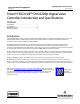
DVC6200p Digital Valve Controller
December 2014
3
Table 1. Specifications
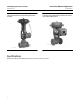
Available Mounting
DVC6200p digital valve controller and DVC6215
feedback unit:
J Integral mounting to the Fisher GX
Control Valve and Actuator System
J Integral
mounting to Fisher rotary actuators,
J Sliding‐stem
linear applications
J Quarter‐turn rotary applications
DVC6205p base unit for 2 inch pipestand or wall
mounting (for remote-mount)
The DVC6200p digital valve controller or DVC6215
feedback unit can also be mounted on other
actuators that comply with IEC 60534-6-1, IEC
60534-6-2, VDI/VDE 3845 and NAMUR mounting
standards.
Function Block Suite
Standard Control (throttling control) includes AO, AI,
DO, and DI function blocks. Also included are a
Logbook block and an Alarm Transducer block.
Function Block Execution Times
AO Block: 6 ms
AI Block: 6 ms
DO Block: 6 ms
DI Block: 6 ms
Electrical Input
Voltage Level: 9 to 32 volts
Maximum Current: 19 mA
Reverse Polarity Protection: Unit is not polarity
sensitive
Termination: Bus must be properly terminated per
ISA SP50 guidelines
Digital Communication Protocol
PROFIBUS registered device
Certified to PROFIBUS Profile 3.02
Physical Layer Type(s):
121—Low-power signaling, bus‐powered, Entity
Model I.S.
511—Low-power signaling, bus‐powered, FISCO I.S.
Supply Pressure
(1)
Minimum Recommended: 0.3 bar (5 psig) higher
than maximum actuator requirements
Maximum: 10.0 bar (145 psig) or maximum pressure
rating of the actuator, whichever is lower
Supply Medium
Air or Natural Gas
Air: Supply pressure must be clean, dry air that meets
the requirements of ISA Standard 7.0.01.
Natural Gas: Natural Gas must be clean, dry, oil‐free,
and noncorrosive. H
2
S content should not exceed 20
ppm.
Filtering and Air Handling
A maximum 40 micrometer particle size in the air
system is acceptable. Further filtration down to 5
micrometer particle size is recommended. Lubricant
content is not to exceed 1 ppm weight (w/w) or
volume (v/v) basis. Condensation in the air supply
should be minimized.
Per ISO 8573-1
Maximum particle density size: Class 7
Oil content: Class 3
Pressure Dew Point: Class 3 or at least 10 K less than
the lowest ambient temperature expected
Output Signal
Pneumatic signal, up to full supply pressure
Minimum Span: 0.4 bar (6 psig)
Maximum Span: 9.5 bar (140 psig)
Action:
J Double, J Single Direct or J Reverse
Steady-State Air Consumption
(2)(3)
Standard Relay
At 1.4 bar (20 psig) supply pressure:
Less than 0.38 normal m
3
/hr (14 scfh)
At 5.5 bar (80 psig) supply pressure:
Less than 1.3 normal m
3
/hr (49 scfh)
Low Bleed Relay
At 1.4 bar (20 psig) supply pressure:
Average value 0.056 normal m
3
/hr (2.1 scfh)
At 5.5 bar (80 psig) supply pressure:
Average value 0.184 normal m
3
/hr (6.9 scfh)
-continued-