
Quick Start Guide


Quick Start Guide
D103203X012
DVC2000 Digital Valve Controller
April 2014
12
5. Tighten the fasteners and remove the alignment template. Continue on with the appropriate step 6 below.
Note
Use a flat end hex key to tighten the mounting assembly fasteners to a torque of 2.37 N•m (21 in•lbf) for 4 mm screws, and
5.08 N•m (45 in•lbf) for 5 mm screws. While tightening the fasteners using the hex key should be sufficient, blue (medium) thread
locker may be used for additional security.
For Air‐to‐Open GX Actuators
6. Remove the top plug (R1/8) from the back of the DVC2000 housing. This pneumatic output port on the DVC2000
lines up with the integral GX actuator pneumatic port. See figure 12.
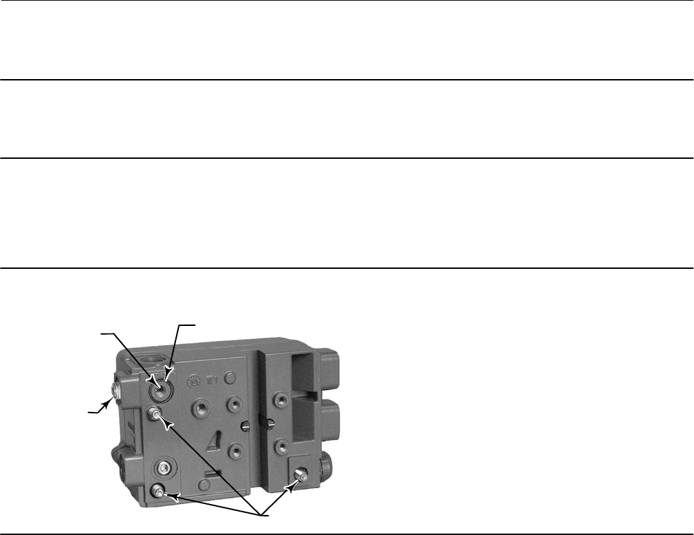
Figure 12. Modifications for Fisher GX Actuator - Air‐to‐Open Construction Only
W9019
REMOVE THE
R1/8 PLUG
ADD THE 1/4 NPT
OR G1/4 PLUG
INSTALL THE O‐RING BEFORE
ASSEMBLING TO THE GX ACTUATOR
M8 MOUNTING BOLTS
7. Install the plug (either G1/4 or 1/4 NPT, included in the mounting kit) to the external output pneumatic port.
8. Remove the cover of the digital valve controller.
9. Using a 6 mm hex wrench, attach the digital valve controller to the GX actuator mounting pad on the side that has
the open pneumatic port. Be sure to place the O‐ring between the digital valve controller's pneumatic output and
the actuator mounting pad. Pneumatic tubing is not required because the air passages are internal to the actuator.
10. Check for clearance between the magnet assembly and the DVC2000 feedback slot. The magnet assembly should
be positioned so that the index mark in the feedback slot of the DVC2000 housing is within the valid range on the
magnet assembly throughout the range of travel. See figure 2.
11. Install a vent in the port on the upper diaphragm casing's air supply connection on the actuator yoke leg.