Quick Start Guide DVC2000 Digital Valve Controller D103203X012 April 2014 Fisher FIELDVUE™ DVC2000 Digital Valve Controller Contents Using this Guide . . . . . . . . . . . . . . . . . . . . . . . . . . . . . . 4 Installation . . . . . . . . . . . . . . . . . . . . . . . . . . . . . . . . . . 5 Basic Setup and Calibration . . . . . . . . . . . . . . . . . . . . 18 Specifications . . . . . . . . . . . . . . . . . . . . . . . . . . . . . . . 29 Related Documents . . . . . . . . . . . . . . . . . . . . . .
Quick Start Guide DVC2000 Digital Valve Controller D103203X012 April 2014 Local Interface Flow Chart These items are identified by an alert icon on the default screen TRAVEL = 66.8% 14.6 MA 0.92 BAR Y 1 Y Home Screen TRAVEL DEVIATION SHUTDOWN ACTIVATED ! CHECK MOUNTING CHECK I/P CONVERTER CHECK SUPPLY Y FINDING 0% ... Y FINDING 50% ... FINDING 0% ... Y FINDING 50% ... Y MOVE VALVE TO 0% TRAVEL Y FINDING 50% ...
Quick Start Guide DVC2000 Digital Valve Controller D103203X012 April 2014 Y Y FW3:1, HW1:2 TUNING = C Y SWITCH1 = OPEN SWITCH 2 = CLOSED Y Y REPLACE MAIN BOARD Y Only when transmitter / limit switch hardware is installed PROTECTION OFF 1 OFF ON Y Y Y QUICK SETUP COMPLETE 1 CALIBRATION COMPLETE 1 CALIBRATION FAILED 1 Y SAVE AND PRESS EXIT? + INVERT DISPLAY 180 Note: Hold + for 3 to 10 seconds + CANCEL (TAKES YOU TO THE HOME SCREEN) Note: Hold + for 3 to 10 seconds
DVC2000 Digital Valve Controller April 2014 Quick Start Guide D103203X012 Use of this Guide This guide describes how to install the digital valve controller and setup and calibrate using the local operator interface. The interface consists of a liquid crystal display, four pushbuttons, and a switch for position transmitter configuration. The DVC2000 is supplied with one of three different language packs preinstalled, depending on the firmware revision and ordering option.
Quick Start Guide DVC2000 Digital Valve Controller D103203X012 April 2014 Installation Note The DVC2000 is not designed to correct for significant stem rotation on sliding stem actuators. WARNING Avoid personal injury or property damage from sudden release of process pressure or bursting of parts. Before mounting the DVC2000 digital valve controller: D Always wear protective clothing, gloves, and eyewear when performing any installation procedures.
Quick Start Guide DVC2000 Digital Valve Controller D103203X012 April 2014 The DVC2000 housing is available in four different configurations, depending on the actuator mounting method and threaded connection style. Figure 1 shows the available configurations. Figure 1.
Quick Start Guide DVC2000 Digital Valve Controller D103203X012 April 2014 Note As a general rule, do not use less than 50% of the magnet array for full travel measurement. Performance will decrease as the array is increasingly subranged. The linear magnet arrays have a valid travel range indicated by arrows molded into the piece. This means that the hall sensor (on the back of the DVC2000 housing) has to remain within this range throughout the entire valve travel. See figure 2.
Quick Start Guide DVC2000 Digital Valve Controller D103203X012 April 2014 Sliding-Stem (Linear) Actuators 1. Isolate the control valve from the process line pressure and release pressure from both sides of the valve body. Shut off all pressure lines to the actuator, releasing all pressure from the actuator. Use lock‐out procedures to be sure that the above measures stay in effect while you work on the equipment. 2. Attach the mounting bracket to the actuator. 3.
Quick Start Guide DVC2000 Digital Valve Controller D103203X012 April 2014 6. Tighten the fasteners and remove the alignment template. Note Use a flat end hex key to tighten the mounting assembly fasteners to a torque of 2.37 N•m (21 in•lbf) for 4 mm screws, and 5.08 N•m (45 in•lbf) for 5 mm screws. While tightening the fasteners using the hex key should be sufficient, blue (medium) thread locker may be used for additional security. 7.
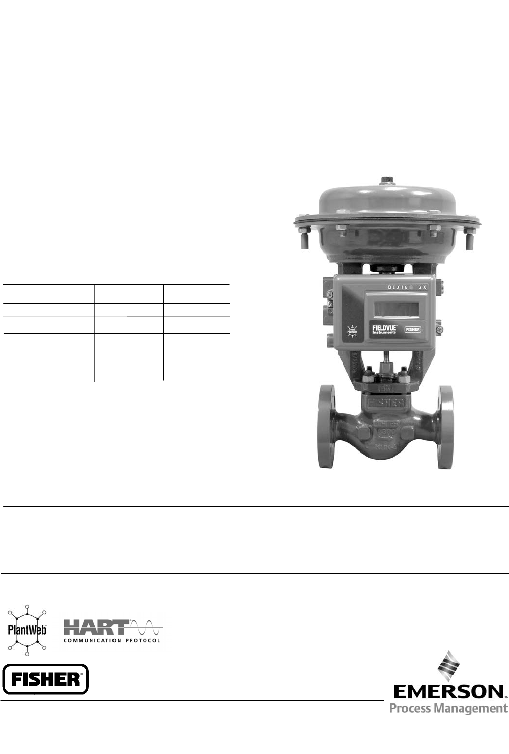
Quick Start Guide DVC2000 Digital Valve Controller D103203X012 April 2014 Mounting on GX Actuators The DVC2000 digital valve controller mounts directly on the GX actuator without the need for a mounting bracket. However, in applications where the process temperature exceeds 80_C (176_F), it may be necessary to apply an insulating gasket between the actuator yoke and the DVC2000, as shown in figure 8.
Quick Start Guide DVC2000 Digital Valve Controller D103203X012 April 2014 If the process and ambient temperatures exceed the limits indicated by zone 2, then the DVC2000 high temperature mounting kit can not be used. If temperatures exceed zone 2, you must use an extension bonnet or bracket mounted instrument. Identify the yoke side to mount the DVC2000 digital valve controller based on the actuator fail mode. Refer to the GX Control Valve and Actuator System instruction manual (D103175X012). 1.
Quick Start Guide DVC2000 Digital Valve Controller D103203X012 April 2014 5. Tighten the fasteners and remove the alignment template. Continue on with the appropriate step 6 below. Note Use a flat end hex key to tighten the mounting assembly fasteners to a torque of 2.37 N•m (21 in•lbf) for 4 mm screws, and 5.08 N•m (45 in•lbf) for 5 mm screws. While tightening the fasteners using the hex key should be sufficient, blue (medium) thread locker may be used for additional security.
Quick Start Guide DVC2000 Digital Valve Controller D103203X012 April 2014 Air‐to‐Close GX Actuators 6. Remove the cover of the digital valve controller. 7. Using a 6 mm hex wrench, attach the digital valve controller to the GX actuator mounting pad. Note The O‐ring and G1/4 or 1/4 NPT plugs (supplied in the mounting kit) are not used with this actuator construction. 8. Check for clearance between the magnet assembly and the DVC2000 feedback slot.
Quick Start Guide DVC2000 Digital Valve Controller D103203X012 April 2014 Guidelines for Mounting on Quarter‐Turn (Rotary) Actuators The DVC2000 digital valve controller can be mounted to any quarter‐turn (rotary) actuator, as well as those that comply with the NAMUR guidelines. A mounting bracket and associated hardware are required. Refer to figure 13. Figure 13. For Rotary Actuators (with Typical Mounting Bracket Shown) M6 MOUNTING BOLTS (4) W8835 1.
Quick Start Guide D103203X012 DVC2000 Digital Valve Controller April 2014 Electrical and Pneumatic Connections The electrical and pneumatic connections on the digital valve controller are available with the following combinations: D 1/4 NPT supply and output with 1/2 NPT conduit connections D G1/4 supply and output with M20 conduit connections Supply Connections WARNING Severe personal injury or property damage may occur from process instability if the instrument air supply is not clean, dry and oil‐free
Quick Start Guide DVC2000 Digital Valve Controller D103203X012 April 2014 Wire the digital valve controller as follows: 1. Remove the main instrument cover. 2. Route the field wiring into the terminal box through the conduit connection. When applicable, install conduit using local and national electrical codes that apply to the application. 3. Connect the control system output card positive wire “current output” to the +11 terminal.
Quick Start Guide DVC2000 Digital Valve Controller D103203X012 April 2014 4. If a second switch is to be used, connect the control system input card positive wire “switch input” to the +51 terminal. Connect the control system input card negative wire “switch input” to the -52 terminal. 5. Proceed to the Basic Setup section to configure the switch action. 6. Replace the cover if the local interface is not being used for configuration or calibration.
Quick Start Guide DVC2000 Digital Valve Controller D103203X012 April 2014 Basic Setup and Calibration The local operator interface is available on all DVC2000 digital valve controllers. The interface consists of a liquid crystal display, four pushbuttons, and a switch for position transmitter configuration. The DVC2000 is supplied with one of three different language packs preinstalled, depending on the firmware revision and ordering option. Language pack options are shown in table 1.
Quick Start Guide DVC2000 Digital Valve Controller D103203X012 April 2014 Basic Setup WARNING Changes to the instrument setup may cause changes in the output pressure or valve travel. Depending on the application, these changes may upset process control which may result in personal injury or property damage. When the DVC2000 digital valve controller is ordered as part of a control valve assembly, the factory mounts the digital valve controller and sets up the instrument as specified on the order.
Quick Start Guide DVC2000 Digital Valve Controller D103203X012 April 2014 Quick Setup When installing the DVC2000 digital valve controller on an actuator for the first time, the quick setup procedure will calibrate and tune the instrument automatically. Table 2 lists the values that are preconfigured at the factory. Table 2.
Quick Start Guide DVC2000 Digital Valve Controller D103203X012 April 2014 Travel Calibration WARNING During calibration the valve will move full stroke. To avoid personal injury and property damage caused by the release of pressure or process fluid, isolate the valve from the process and equalize pressure on both sides of the valve or bleed off the process fluid.
Quick Start Guide DVC2000 Digital Valve Controller D103203X012 April 2014 Tuning WARNING Changes to the tuning set may cause the valve/actuator assembly to stroke. To avoid personal injury and property damage caused by moving parts, keep hands, tools, and other objects away from the valve/actuator assembly. To manually tune the instrument or automatically tune the instrument without changing the calibration values, the TUNING routine is available.
Quick Start Guide DVC2000 Digital Valve Controller D103203X012 April 2014 Table 3. Gain Values for Preselected Turning Sets Tuning Set Proportional Gain Velocity Gain Minor Loop Feedback Gain C 5 2 55 D 6 2 55 E 7 2 55 F 8 2 52 G 9 2 49 H 10 2 46 I 11 2 44 J 12 1 41 K 14 1 38 L 16 1 35 M 18 1 35 A typical starting point for most small actuators is “C”. Using the UP (Y) and DOWN (B) arrow keys will apply the values immediately.
Quick Start Guide DVC2000 Digital Valve Controller D103203X012 April 2014 The factory default characteristic is LINEAR. You can also use a QUICK OPEN, EQUAL %, or CUSTOM function. However, the custom function is initially configured linear, unless you use a HART based host to reconfigure the custom points. Custom configuration can be selected, but the curve cannot be modified with the local interface. Figure 20. Detailed Setup Flow Chart TRAVEL = 66.8% 14.6 MA 0.
Quick Start Guide DVC2000 Digital Valve Controller D103203X012 April 2014 Figure 21. XMTR Switch TRANSMITTER SWITCH FOR FAIL SIGNAL + HIGH (SHOWN) OR -LOW W8839 Switch #1 Trip Point—Defines the threshold for the limit switch wired to terminals +41 and -42 in percent of calibrated travel. Switch #1 Closed—Configures the action of the limit switch wired to terminals +41 and -42. Selecting ABOVE configures the switch to be closed when the travel is above the trip point.
Quick Start Guide DVC2000 Digital Valve Controller D103203X012 April 2014 Figure 22. Position Transmitter Calibration TRAVEL = 66.8% 14.6 MA 0.
Quick Start Guide DVC2000 Digital Valve Controller D103203X012 April 2014 The UP (Y) and DOWN (B) arrow keys will allow you to change the setpoint and therefore move the valve manually. To exit the manual mode, use the LEFT (A) arrow key to return to the choice list. Select ANALOG. Note When placing the instrument back into ANALOG, the valve will step back to the position commanded by the input current. Figure 23. Local Control TRAVEL = 66.8% 14.6 MA 0.
DVC2000 Digital Valve Controller April 2014 Quick Start Guide D103203X012 Once switch circuit 1 is powered properly, question marks (???) will indicate that the corresponding switch is disabled. Shutdown Activated— This screen appears if the positioner has shut down and no air is being delivered to the actuator. Therefore, the valve is at its fail‐safe position. An example of a source of this error is corrupt firmware code upon start‐up. The factory default setting for this error is disabled.
Quick Start Guide DVC2000 Digital Valve Controller D103203X012 April 2014 Specifications Air Consumption(2) Available Configurations Supply pressure At 1.5 bar (22 psig) (3): 0.06 normal m3/h (2.3 scfh) At 4 bar (58 psig) (4): 0.12 normal m3/h (4.
Quick Start Guide DVC2000 Digital Valve Controller D103203X012 April 2014 Specifications (continued) Other Classifications/Certifications GOST‐R—Russian GOST‐R INMETRO—National Institute of Metrology, Quality and Technology (Brazil) KGS— Korea Gas Safety Corporation (South Korea) NEPSI—National Supervision and Inspection Centre for Explosion Protection and Safety of Instrumentation (China) PESO CCOE—Petroleum and Explosives Safety Organisation - Chief Controller of Explosives (India) RTN—Russian Rostekh
Quick Start Guide DVC2000 Digital Valve Controller D103203X012 April 2014 Table 4.
DVC2000 Digital Valve Controller Quick Start Guide April 2014 D103203X012 Related Documents Other documents containing information related to the DVC2000 digital valve controller include: D Bulletin 62.
Quick Start Guide D103203X012 DVC2000 Digital Valve Controller April 2014 Hazardous Area Classifications and Special Instructions for “Safe Use” and Installations in Hazardous Locations Certain nameplates may carry more than one approval, and each approval may have unique installation/wiring requirements and/or conditions of “safe use”. These special instructions for “safe use” are in addition to, and may override, the standard installation procedures. Special instructions are listed by approval.
Quick Start Guide DVC2000 Digital Valve Controller D103203X012 April 2014 Figure 25. CSA Installation Drawing EQUIPMENT SHALL BE INSTALLED IN ACCORDANCE WITH THE CANADIAN ELECTRICAL CODE (CEC) PART 1: BARRIERS MUST BE CSA APPROVED WITH ENTITY PARAMETERS AND ARE TO BE INSTALLED IN ACCORDANCE WITH THE MANUFACTURER'S I.S. INSTALLATION INSTRUCTIONS. THE ENTITY CONCEPT ALLOWS INTERCONNECTION OF INTRINSICALLY SAFE APPARATUS TO ASSOCIATED APPARATUS, NOT SPECIFICALLY EXAMINED IN SUCH COMBINATION.
Quick Start Guide DVC2000 Digital Valve Controller D103203X012 April 2014 Figure 26. Typical FM Nameplate Figure 27. FM Installation Drawing INSTALLATION MUST BE IN ACCORDANCE WITH THE NATIONAL ELECTRICAL CODE (NEC) AND ANSI/ISA RP12.6. BARRIERS MUST BE CONNECTED PER MANUFACTURER'S INSTALLATION INSTRUCTIONS. THE ENTITY CONCEPT ALLOWS INTERCONNECTION OF INTRINSICALLY SAFE APPARATUS TO ASSOCIATED APPARATUS, NOT SPECIFICALLY EXAMINED IN SUCH COMBINATION.
DVC2000 Digital Valve Controller April 2014 Quick Start Guide D103203X012 ATEX Special Conditions for Safe Use Intrinsically Safe The equipment is an intrinsically safe equipment. It can be mounted in hazardous area. The terminal blocks can be only connected to certified intrinsically safe equipments and these combinations must be compatible as regard intrinsic safety rules. The equipment shall be connected in accordance with manufacturer's installation instructions in drawing GE14685 (figure 29).
Quick Start Guide DVC2000 Digital Valve Controller D103203X012 April 2014 Figure 29. ATEX Installation Drawing INSTALLATION MUST BE IN ACCORDANCE WITH THE NATIONAL WIRING PRACTICES OF THE COUNTRY IN USE. BARRIERS MUST BE CONNECTED PER MANUFACTURER'S INSTALLATION INSTRUCTIONS. WARNING THE APPARATUS ENCLOSURE CONTAINS ALUMINUM AND IS CONSIDERED TO CONSTITUTE A POTENTIAL RISK OF IGNTION BY IMPACT OR FRICTION. CARE MUST BE TAKEN DURING INSTALLATION AND USE TO PREVENT IMPACT OR FRICTION.
DVC2000 Digital Valve Controller Quick Start Guide D103203X012 April 2014 IECEx Conditions of Certification Intrinsically Safe This equipment shall be connected in accordance with the manufacturer's installation instructions (drawing GE14581, figure 31) to intrinsic safety barriers that satisfy the following parameters for each set of terminals. Main 4-20 mA: Ui = 30 V, Ii = 130 mA, Pi = 1W, Li = 0.55 mH, Ci = 10.
Quick Start Guide DVC2000 Digital Valve Controller D103203X012 April 2014 Figure 31. IECEx Installation Drawing INSTALLATION MUST BE IN ACCORDANCE WITH THE NATIONAL WIRING PRACTICES OF THE COUNTRY IN USE. WARNING THE APPARATUS ENCLOSURE CONTAINS ALUMINUM AND IS CONSIDERED TO CONSTITUTE A POTENTIAL RISK OF IGNTION BY IMPACT OR FRICTION. CARE MUST BE TAKEN DURING INSTALLATION AND USE TO PREVENT IMPACT OR FRICTION. BARRIERS MUST BE CONNECTED PER MANUFACTURER'S INSTALLATION INSTRUCTIONS.
DVC2000 Digital Valve Controller April 2014 Quick Start Guide D103203X012 Neither Emerson, Emerson Process Management, nor any of their affiliated entities assumes responsibility for the selection, use or maintenance of any product. Responsibility for proper selection, use, and maintenance of any product remains solely with the purchaser and end user.