
Instruction Manual


Instruction Manual Supplement
D103261X012
DVC6000/DVC6200 Digital Valve Controllers
February 2011
6
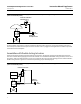
Figure 5. Lock‐in‐Last on Loss of Loop Current and/or Supply Pressure for an Assembly with a Single‐Acting Actuator
(Fisher DVC6000 Depicted)
PHOENIX
SWITCH
MCR‐2SP/UI
A
C
2
3
D
1
B
+
-
+-
+
+
-
-
2
1
12
87
13
FISHER 67CFR
FILTER/REGULATOR
AIR
SUPPLY
SOLENOID VALVE
(ENERGIZED)
24 VDC
POWER SUPPLY
FISHER 164A
THREE‐WAY
SWITCHING VALVE
4‐20
mA
OUTPUT
SUPPLY
DIGITAL
VALVE
CONTROLLER
1
NOTE:
THE ASCO 8320 SERIES SOLENOID VALVE OR EQUIVALENT IS APPROPRIATE FOR THIS ASSEMBLY.
1
Upon loss of loop current, the relay of the current threshold switch opens. This cuts power to the solenoid valve,
causing the solenoid valve to trip. When the solenoid valve trips, the supply pressure that was holding the switching
valve open is exhausted to atmosphere. This simulates a loss of supply pressure, causing the switching valve to trip.
Note
Use a single power source for both the analog output (AO) card providing loop current to the digital valve controller and the
solenoid valve. This ensures power will be maintained to the solenoid valve so long as power is maintained to the AO card.
Assemblies with Double‐Acting Actuators
The same principle used for assemblies with single‐acting actuators is used for assemblies with double‐acting
actuators. Figure 6 is a schematic of the double‐acting assembly with lock‐in‐last capability shown under normal
operating conditions.