
Instruction Manual


Instruction Manual Supplement
D103261X012
DVC6000/DVC6200 Digital Valve Controllers
February 2011
5
The solenoid valve in this solution does not require a C
v
greater than 0.49. Flow capacity of this valve can be much
smaller. An example of a proper solenoid valve for this assembly is the 8320 Series three‐way solenoid valve. As with all
solenoid valves, ensure that the solenoid valve operating pressure differential rating is adequate for the supply
pressure.
Lock‐in‐Last on Loss of Supply Pressure and/or Loss of Loop
Current
Most applications require a valve assembly to be in a lock‐in‐last fail state not only on loss of adequate supply pressure
but also on loss of loop power. Lock‐in‐last on loss of supply pressure is quite straight forward. Lock‐in‐last on loss of
loop power can be more complex.
Most control loops operate on a 4‐20 mA control signal. A solenoid valve, adequately sized for the application, requires
more than 4 mA to energize. Therefore, the control loop cannot be used to energize the solenoid. Instead the solenoid
must be powered by a separate 24 volt power source. Thus an additional device is required to monitor the current to
the digital valve controller and control the power to the solenoid.
A current threshold switch can be used to monitor the 4‐20 mA signal to the digital valve controller. Upon loss of this
signal, or when the signal falls below the threshold, the threshold switch will open an internal relay. This relay, if placed
between a solenoid valve and its power supply, will essentially open and close the solenoid valve. The solenoid valve
can be placed in line with the tubing to the actuator to provide the lock‐in‐last function.
To ensure adequate response time of a locking system to a loss of loop current, a threshold switch with a maximum
deadtime of 0.025 seconds should be used. The locking system will be faster than the response of the positioning
system to the failure.
One switch that meets the maximum deadtime requirements is the Phoenix Contact Dual Setpoint Module, Model
MCR‐2SP/UI.
Note
The MCR‐2SP/UI switch is not provided by Emerson Process Management. Order this switch from Phoenix Contact.
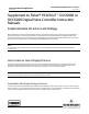
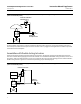
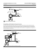
Assemblies with Single‐Acting Actuators
Assemblies with a single‐acting actuator use a 164A three‐way switching valve in conjunction with a solenoid valve.
Figure 5 is a schematic of a single‐acting actuator assembly with lock‐in‐last capability on loss of supply pressure or
loop current. Under normal operating conditions power is supplied to the solenoid valve and adequate supply pressure
is available to the switching valve. Upon loss of supply pressure, the set point of the switching valve is exceeded and
the switching valve trips.