
Instruction Manual


Instruction Manual Supplement
D103261X012
DVC6000/DVC6200 Digital Valve Controllers
February 2011
3
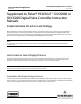
Connection of the digital valve controller output to a double‐acting actuator determines the action of the actuator.
Figure 2 shows the digital valve controller providing lower cylinder pressure through ports D and E, and upper cylinder
pressure through ports A and B. When the supply pressure falls below the set point of the trip valve, the trip valve
closes ports D and A and connects port B to C and port E to F. Because C and F are plugged, the control valve is locked
in place by locking pressure on both sides of the actuator piston. The assembly returns to normal operation once
supply pressure is restored at the trip valve INPUT port.
Note
Double‐acting actuators with a 377L trip valve require a Fisher 64 or 95H regulator. Regulators with smaller flow capacities may
cause the trip valve to cycle (lock and unlock repeatedly) due to air flow demand as the assembly attempts to reset. Use a Fisher
252 or 262C pilot filter to filter supply air.
Both the 164A switching valve and the 377L trip valve have a deadband that must be overcome. The switching valve must be
calibrated to reset upon restoration of adequate supply pressure to the regulator. The 377L trip valve has only one spring
selection. However, for minimal deadband, the lightest appropriate spring should be selected for the 164A switching valve.
Lock‐in‐Last Using Solenoid Valves
Solenoid valves are used with valve assemblies in many ways. Their electrical control can be utilized in combination
with switches and controller logic to perform a number of functions.
Note
Solenoid valves placed between the output of a DVC6000 or DVC6200 digital valve controller and the input to an actuator require
a minimum C
v
of 0.49. Greater restrictions can affect the response of the assembly. An example of an appropriate three‐way
solenoid valve for use with the digital valve controller is the ASCO™ 8327 Series solenoid valve from ASCO Valve, Inc.
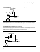
Assemblies with Single‐Acting Actuators
A three‐way universal solenoid valve can be placed between the digital valve controller output and the actuator input.
Switching the valve assembly from an unlocked state to a locked state is controlled by switching power on and off to
the solenoid valve. Figure 3 depicts proper assembly layout.
Under normal operating conditions the solenoid is energized and supply air flows from the digital valve controller
output to the actuator input. In the fail state, power is removed from the solenoid causing the solenoid valve to close,
locking air pressure in the actuator. Port 1 of the solenoid valve is plugged, preventing actuator air pressure from
exhausting to the atmosphere.