
Instruction Manual


Instruction Manual Supplement
D103261X012
DVC6000/DVC6200 Digital Valve Controllers
February 2011
2
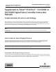
Figure 1. Lock‐in‐Last on Loss of Supply Pressure for an Assembly with a Single‐Acting Actuator
(Fisher DVC6000 Depicted)
FISHER 164A THREE‐WAY
SWITCHING VALVE
A
C
D
B
FISHER 67CFR
FILTER/REGULATOR
AIR
SUPPLY
SUPPLY
OUTPUT
DIGITAL
VALVE
CONTROLLER
In a fail condition, the pressure at port D is below the switching valve's set point, causing the switching valve to trip.
This closes port B, which locks the pressure in the actuator. Port C is plugged so the digital valve controller output will
not exhaust to the atmosphere.
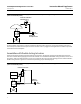
Assemblies with Double‐Acting Actuators
Similar to the locking strategy used with single‐acting actuators, the locking strategy with double‐acting actuators
also uses a valve for locking supply pressure in the actuator. For assemblies with double‐acting actuators, a Fisher 377L
trip valve is used as the locking device. The 377L trip valve has two output ports for locking pressure on both sides of a
double‐acting actuator. Figure 2 is a schematic representing proper assembly layout.
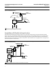
Figure 2. Lock‐in‐Last on Loss of Supply Pressure for an Assembly with a Double‐Acting Actuator
(Fisher DVC6000 Depicted)
FISHER 377L TRIP VALVE
E
D
F
C
B
A
FISHER 64
REGULATOR
AIR
SUPPLY
OUTPUT
SUPPLY
INPUT
OUTPUT
DIGITAL
VALVE
CONTROLLER