
Instruction Manual


Instruction Manual Supplement
D103262X012
FIELDVUE Digital Valve Controllers
February 2011
5
Configuration
Current flowing through the input terminal of the isolator is regenerated at the output terminals of the isolator (at a
higher voltage) and flows through the second FIELDVUE instrument only. Input ranging of the FIELDVUE instruments is
easily changed without recalibrating. This is done by configuring the Input Range Low and the Input Range High to the
desired values. A typical configuration would be:
FIELDVUE Instrument Input Range Low Input Range High Polling Address
#1
#2
4 mA
12 mA
12 mA
20 mA
0
0
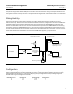
Multiple Split Range
The installation described for the alternate method can be extended to multiple instruments, as shown in figure 3. This
architecture allows up to four units to be split ranged. Due to an increase in the signal to noise ratio as the input span
decreases, the minimum input span should be limited to 4 mA. Be aware that as the number of units to be split ranged
increases, the accuracy of each unit is affected.
Figure 3. Typical Multiple Split Range Installation
− +
− +
− +
− +
Controller
Action
Instruments
AP4380-2000
Isolator
120VAC
DC
4-20 mA
+−
FIELDVUE Instrument #1
Input Range: 4-8 mA
FIELDVUE Instrument #2
Input Range: 8-12 mA
Hazardous Location
Non-Hazardous Location
−
+
+−
Action
Instruments
AP4380-2000
Isolator
Action
Instruments
AP4380-2000
Isolator
− +
− +
− +
− +
++−−
120VAC 120VAC
FIELDVUE Instrument #3
Input Range: 12-16mA
FIELDVUE Instrument #
4
Input Range: 16-20 mA
−−++4-20 mA Out 4-20 mA Out4-20 mA Out
4-20 mA Analog In
4-20 mA Analog In 4-20 mA Analog In
HART Polling Address 0
HART Polling Address 0
HART Polling Address 0
HART Polling Address 0
LOOP
Terminals
LOOP
Terminals
LOOP
Terminals
LOOP
Terminals
LOOP
Terminals