
Instruction Manual


Instruction Manual Supplement
D103262X012
FIELDVUE Digital Valve Controllers
February 2011
4
Installation—Alternate Method
When connecting two instruments in series for this split range application, the compliance voltage requirement from
the DCS controller is much lower. This is because the Action Instruments AP4380‐2000 is in series with the first
FIELDVUE instrument and requires minimum voltage (0.3 volts). The isolator powers only the second FIELDVUE
instrument and therefore provides adequate voltage.
Wiring Hook‐Up
The Action Instruments product bulletin describes the product details and limitations (available on the web at
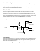
www.actionio.com). These should be read and observed. The connections are shown in figure 2. For a typical
installation, connect the control system positive (+) output terminal to the AP4380‐2000 positive (+) input terminal.
Connect the AP4380‐2000 input negative (-) terminal to the first FIELDVUE instrument LOOP + terminal. Connect the
first FIELDVUE instrument LOOP - terminal to the control system negative (-) terminal. Connect the AP4380‐2000
positive (+) output terminal to the second FIELDVUE instrument LOOP + terminal. Connect the AP4380‐2000 negative
(-) output terminal to the second FIELDVUE instrument LOOP - terminal.
Figure 2. Typical Installation Schematic, Alternate Method
− +
− +
− +
− +
Controller
Action
Instruments
AP4380-2000
Isolator
120VAC
DC
4-20 mA
+−
FIELDVUE Instrument #1
Input Range: 4-12 mA
FIELDVUE Instrument #2
Input Range: 12-20 mA
Hazardous Location
Non-Hazardous Location
−
+
+
−
4-20 mA Out
4-20 mA Analog In
HART Polling Address 0
HART Polling Address 0
HART Tri‐Loop (optional)
HART Polling Address 1
HART Tri‐Loop
(optional)
HART Polling Address 1
LOOP
Terminals
LOOP
Terminals