
Instruction Manual


Instruction Manual Supplement
D103262X012
FIELDVUE Digital Valve Controllers
February 2011
3
compliance voltage of the AP4380-2000 prior to shipment. This should be done using the technique described in the
instrument instruction manual. Generally, a compliance voltage of 25 volts DC at 20 mA output with a guaranteed line
voltage of 120 volts AC is adequate for normal lengths of field wiring.
Wiring Hook‐Up
The Action Instruments product bulletin describes the product details and limitations (available on the web at
www.actionio.com). These should be read and observed. Before installation, configure each instrument with different
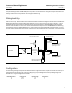
HART polling addresses (example HART polling addresses 2 and 3). The connections are shown in figure 1. A typical
installation has the control system 4‐20 mA DC output signal connected to the AP4380-2000 input terminals. The
isolator can be installed in the rack room. Connect the 4‐20 mA DC output from the AP4380‐2000 to the field wiring.
In the field, connect the AP4380‐2000 positive (+) output terminal to the first FIELDVUE instrument LOOP + terminal.
Connect the first FIELDVUE instrument LOOP - terminal to the second FIELDVUE instrument LOOP + terminal. Connect
the second FIELDVUE instrument LOOP - terminal to the AP4380-2000 negative (-) output terminal.
Figure 1. Typical Installation Schematic, Traditional Method
− +
− +
− +
− +
Controller
Action
Instruments
AP4380-2000
Isolator
120VAC
DC
4-20 mA
+
−
FIELDVUE Instrument #1
HART Polling Address 2
Input Range: 4-12 mA
FIELDVUE Instrument #2
HART Polling Address 3
Input Range: 12-20 mA
LOOP
4-20 mA
Hazardous LocationNon-Hazardous Location
HART Tri‐Loop (optional)
HART Polling Address 1
Terminals
LOOP
Terminals
Configuration
Current flowing through the input terminals of the isolator is regenerated at the output terminals of the isolator (at a
higher voltage) and flows through both FIELDVUE instruments. Input ranging of the FIELDVUE instruments is easily
changed without recalibrating. This is done by configuring the Input Range Low and the Input Range High to the
desired values. A typical configuration would be:
FIELDVUE Instrument Input Range Low Input Range High Polling Address
#1
#2
4 mA
12 mA
12 mA
20 mA
2
3