
Instruction Manual


Instruction Manual
D100400X012
EWN and EW-1 Valves
July 2014
9
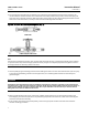
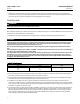
Table 4. Valve Body-to-Bonnet Bolt Torque Guidelines
(1)
VALVE SIZE, NPS
BOLT TORQUES
(2)
FOR FIELD-LUBRICATED BOLTING
NSm LbfSFt
8 x 6 CL900 542 400
12 x 8
CL300 or 600 691 510
CL900 with steel or alloy steel bolting 2440 1800
CL900 with stainless steel bolting 2712 2000
1. For other materials, contact your Emerson Process Management sales office for torques.
2. Determined from laboratory tests.
Note
Proper performance of the tightening procedures in step 9 compresses the outer edge of the bonnet gasket (key 10, figure 7
through 10) enough to seal the valve body-to-bonnet joint.
The bolting procedures in step 9 include -- but are not limited to -- ensuring that bolting threads are clean and evenly tightening
the hex nuts onto the studs in a crisscross pattern. Because of the boltup characteristics of the bonnet gasket, tightening one nut
may loosen an adjacent nut. Repeat the crisscross tightening pattern several times until each nut is tight and the valve
body-to-bonnet seal is made. When the operating temperature has been reached, perform this torquing procedure once again.
Note
Stud(s) and nut(s) should be installed such that the manufacturer's trademark and material grade marking is visible, allowing easy
comparison to the materials selected and documented in the Emerson/Fisher serial card provided with this product.
WARNING
Personal injury or damage to equipment could occur if improper stud and nut materials or parts are used. Do not operate or
assemble this product with stud(s) and nut(s) that are not approved by Emerson/Fisher engineering and/or listed on the
serial card provided with this product. Use of unapproved materials and parts could lead to stresses exceeding the design
or code limits intended for this particular service. Install studs with the material grade and manufacturer's identification
mark visible. Contact your Emerson Process Management representative immediately if a discrepancy between actual
parts and approved parts is suspected.
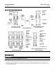
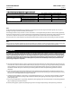
9. Lubricate the stud bolts (key 15, figure 7 through 10) with anti-seize lubricant, slide the bonnet over the stem and
onto the bolts, and secure with the stud bolt nuts (key 16, figure 7 through 10), using accepted bolting procedures
during tightening so that the valve body-to-bonnet joint will withstand test pressures and application service
conditions. The bolt torques in table 4 may be used as guidelines unless accepted bolting procedures dictate
otherwise.
10. Install new packing and the metal packing box parts according to the appropriate arrangement in figure 3 or 4.
Place a smooth-edged pipe over the valve stem, and gently tap each soft packing part into the packing box, being
sure that air is not trapped between adjacent soft parts.
11. Slide the packing follower, upper wiper, and packing flange (keys 13, 12, and 3, figure 6) into position. Lubricate
the packing flange studs (key 4, figure 6) and the faces of the packing flange nuts (key 5, figure 6). Replace the
packing flange nuts.
12. For spring-loaded PTFE V-ring packing, tighten the packing flange nuts until the shoulder on the packing follower
(key 13, figure 6) contacts the bonnet.
For other packing types, tighten the packing flange nuts far enough to stop leakage under operating conditions.