
Instruction Manual


Instruction Manual
D100400X012
EWN and EW-1 Valves
July 2014
6
WARNING
To avoid personal injury or property damage resulting from fire or explosion, do not lubricate packing used in oxygen
service or in processes with temperatures over 260_C (500_F).
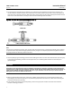
If a lubricator or lubricator/isolating valve (figure 2) is provided for PTFE/composition or other packings that require
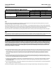
lubrication, it will be installed in place of the 1/4 NPT pipe plug (key 14, figure 6). Use a silicon-base lubricant. Packing
used in oxygen servic e or in processes with temperatures over 260C(500F) should not be lubricated. To operate the
lubricator, turn the cap screw clockwisetoforcethelubricantintothepackingbox.Thelubricator/isolatingvalve
operatesthesamewayexcepttheisolatingvalvemustfirstbe opened and then closed after lubrication is completed.
Packing Maintenance
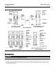
This section covers only PTFE V-ring and PTFE/composition packing. Refer to a separate manual for graphite
laminate/filament packing if used. Key numbers refer to figure 3 for PTFE V-ring packing and to figure 4 for
PTFE/composition packing unless otherwise indicated.
For spring-loaded single PTFE V-ring packing, the spring (key 8, figure 3) maintains a sealing force on the packing. If
leakage is noted around the packing follower (key 13, figure 3), check to be sure the shoulder on the packing follower
is touching the bonnet. If the shoulder is not touching the bonnet, tighten the packing flange nuts (key 5, figure 6)
until the shoulder is against the bonnet. If leakage cannot be stopped in this manner, proceed to the Replacing
Packing section.
If there is undesirable packing leakage with other than spring-loaded packing, first try to limit the leakage and
establish a stem seal by tightening the packing flange nuts.
If the packing is relatively new and tight on the stem and if tightening the packing flange nuts does not stop the
leakage, it is possible that the valve stem is worn or nicked so that a seal cannot be made. The surface finish of a new
valve stem is 0.1 micro-meter (4 micro-inches) rms. If the leakage comes from the outside diameter of the packing, it
is possible that the leakage is caused by nicks or scratches around the packing box wall. If performing any of the
following procedures, inspect the valve stem and packing box wall for nicks and scratches.
Adding Packing Rings
When using packing with a lantern ring (key 8, figure 3 or 4), it is possible to add packing rings above the lantern ring
as a temporary measure without removing the actuator from the valve body.
1. Remove the packing flange nuts (key 5, figure 6), and lift the packing flange and follower (keys 3 and 13, figure 6)
away from the valve body.
2. Itmaybepossibletodigouttheoldpackingringsontopofthelanternring,butusecaretoavoidscratchingthe
valve stem or packing box wall. Clean all metal parts to remove particles that would prevent the packing from
sealing.
3. If split-ring packing is being added, spread the rings over the stem, and slide the rings into the packing box.
If solid-ring packing is being added, remove the stem connector, and slip the rings over the end of the valve stem.
4. Replace the packing flange and packing follower. Tighten the packing flange nuts (key 5, figure 6) only far enough
to stop leakage under operating conditions.
5. If the valve-actuator stem connection was taken apart, reconnect according to the appropriate actuator instruction
manual.
6. Check for leakage around the packing follower when the valve is being put into service. Retighten the packing
flange nuts as required.