
Instruction Manual

Instruction Manual
D100400X012
EWN and EW-1 Valves
July 2014
12
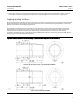
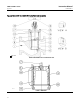
Table 6. Removal Tool Required for Seat Ring Threaded to Valve Body (For 136, 197, or 203 mm (5-3/8, 7-3/4, or
8-inch) Seat Rings)
VALVE SIZE AND
DESIGN
PIPE TO MACHINE
DIMENSION
A CMin D E H J
Size, Inch Schedule mm Inch mm Inch mm Inch mm Inch mm Inch mm Inch
8x6EWN-1Series 5 120 610 24.00 12.7 0.50 63.5 2.50 25.4 1.00 210 8.25 133 5.25
12 x 8
EW-1 Series 8 XXS 678 26.69 69.9 2.75 76.2 3.00
28.6 1.125 246 9.69 194 7.62
EWN-1 Series 8 XXS 825 32.50 69.9 2.75 88.9 3.50
Table 7. Removal Tool Required for Seat Ring Threaded to Valve Body (For 172 mm (6-3/4-inch) Seat Rings)
VALVE SIZE AND DESIGN
PIPE TO MACHINE DIMENSION A
Size, Inch Schedule mm Inch
12 x 8
EW-1 Series 6 XS 678 26.69
EWN-1 Series 6 XS 825 32.50
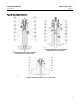
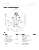
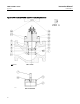
Valve Plug Maintenance
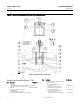
Except where indicated, key numbers in this section are referenced in figures 7and8forEWNSeriesvalveplugsandin
figures 9 and 1 0 for EW-1 Series valve plugs.
CAUTION
Ifreplacingthevalveplugpistonringorsealring(key5),becarefulnottoscratchthesurfacesoftheringgrooveinthe
valve plug or any of the surfaces of the replacement ring, or the replacement ring may not seal properly.
1. With the valve plug (key 2) removed according to the Disassembly section, proceed as appropriate:
For the EWD-1 or EWND-1 graphite piston ring, the ring or rings can be easily removed since each ring is in two halves.
A new graphite piston ring is furnished as a complete ring and must be broken into two approximately equal portions.
Do this by placing the ring horizontally in a vise and applying pressure until the ring snaps. An alternate method is to
placetheringonedgeonasmooth,hardsurfaceandstriketheringsquarelywithahammer.Besuretomatchthe
broken ends when installing the ring in the valve plug groove.
For the EWT-1, EWNT-1, or EWNT-2 spring-loaded seal ring, the ring used on the valve plug for an NPS 8 x 6 valve body
may be removed undamaged by first working the retaining ring (key 13) off with a screwdriver. Then carefully slide the
metal backup ring (key 12) and seal ring (key 5) off the valve plug (key 2). The spring-loaded seal ring used on the valve
plug for an NPS 12 x 8 valve body must be carefully pried and/or cut from its groove. Therefore, it cannot be reused.
A spring-loaded seal ring must be installed so that its open side faces toward either the top or the bottom of the valve
plug, depending on flow direction, as shown in view A of figure 7, 8, or 10. To install a spring-loaded seal ring on the
valve plug for an NPS 8 x 6 valve body, slide the seal ring (key 5) onto the valve plug followed by the metal backup ring
(key 12). Then install the retaining ring (key 13) by inserting one end in the groove and, while turning the plug, press
the ring into the groove. Again, be careful not to scratch any surfaces of the ring or plug.
To install the seal ring on the valve plug for an NPS 12 x 8 valve body, lubricate it with a general purpose silicone-base
lubricant. Then gently stretch the seal ring, and work it over the top edge of the valve plug. The PTFE material in the
seal ring must be permitted time to cold-flow during stretching procedure; so avoid jerking sharply on the ring.
Stretching the seal ring over the valve plug may make it seem unduly loose when in the groove, but it will contract to
its original size after insertion into the cage.