
Instruction Manual


Instruction Manual
D100400X012
EWN and EW-1 Valves
July 2014
10
13. Mount the actuator on the valve body assembly, and reconnect the actuator and valve stem according to the
procedure in the appropriate actuator instruction manual.Checkforleakagearoundthe packing follower when the
valve is being put into service. Retighten the packing flange nuts as required.
Trim Removal
WARNING
Observe the warning at the start of the Maintenance section.
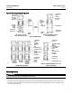
Except where indicated, key numbers in this section are referenced in figures 7 and 8 for EWN Series constructions and
in figures 9 and 10 for EW-1 Series constructions.
1. Remove the actuator and the bonnet according to steps 1 through 5 of the Replacing Packing section.
CAUTION
When lifting the valve plug stem (key 7) and attached valve plug (key 2) out of the valve body, be certain that the cage or
cage assembly (key 3) remains in the valve body (key 1). This is to prevent damage caused by the cage or cage assembly
dropping back into the valve body after being lifted part way out.
Use care to avoid damaging gasket sealing surfaces. Any damage to the gasket sealing surfaces could cause the valve to
leak.
Thegraphitepistonring(key5)inanEWD-1orEWND-1valvebody is brittle and in two pieces. Use care to avoid damage to
the piston ring caused by dropping or rough handling.
The surface finish of the valve stem (key 7) is critical for making a good packing seal. The inside surface of the cage or cage
assembly (key 3) is critical for smooth operation of the valve plug and for making a seal with the piston ring or seal ring
(key 5). The seating surfaces of the valve plug (key 2) and seat ring (key 9) are critical for tight shutoff. Protect these parts
accordingly while disassembling the trim.
Table 5. Pin Replacement
VALVE STEM CONNECTION (VSC)
DRILL SIZE,
INCH
mm Inches
19.1
25.4
31.8
3/4
1
1-1/4
3/16
1/4
1/4
2. Packing parts can be removed if desired. Replace these parts as described in the Packing Replacement section.
3. Lift the valve plug and stem assembly out of the valve body and set it on a protective surface. If the valve plug is to
be reused, protect the valve plug seating surface to prevent scratches.
4. Install screws or bolts into the tapped holes in the top of the cage or cage assembly, and carefully lift it out of the
valve body. Remove the associated gaskets (key 10 and, if used, key 11).
5. The EWNT-2 valve body has a seat ring seal ring (key 6). Inspect this seal ring, and remove it if replacement is
necessary. The EWNT-2 seat ring is screwed into the cage and secured with two tack welds, one on each side of the
cage. The seat ring can be removed by grinding or filing off the tack welds and then inserting a bar through slots cut
intheseatringtoturnitoutofthecage.
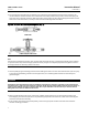
6. To remove the seat ring (key 9) from an EW-1 or EWN-1 Series valve, use a seat ring removal tool made as shown in
figure 5. Use a piece of pipe of the indicated size and schedule, machine as appropriate, and then weld a collar of
the indicated dimensions around the pipe. Engage the seat ring lugs with the 44.5 mm (1-3/4-inch) groove of the
tool, and then remove the seat ring by slipping a suitable length of pipe through the 76.2 mm (3-inch) diameter
hole in the other end of the tool to provide leverage.