
Instruction Manual

Instruction Manual
D100398X012
ET Valve
October 2014
8
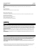
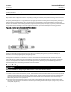
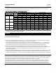
Figure 4. Detail of PTFE/Composition Packing Arrangements for Plain and Extension Bonnets
UPPER WIPER
(KEY 12)
PACKING
FOLLOWER (KEY 13)
LANTERN RING
(KEY 8)
PACKING BOX
RING (KEY 11)
PACKING RING
(KEY 7)
9.5 mm
(3/8 INCH)
STEM
12.7 mm
(1/2 INCH)
STEM
19.1, 25.4, OR
31.8 mm
(3/4,1,OR
1-1/4 INCH)
STEM
12A8188-A
12A7815-A
12A8173-A
A2619-1
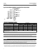
Table 3. Body-to-Bonnet Bolt Torque Guidelines
VALVE SIZE, NPS BOLT TORQUES
(1)
ET EAT
SA193-B7, SA193-B8M
(3, 4)
SA193-B8M
(2, 4)
NSm LbfSft NSm LbfSft
1-1/4 or less 1 129 95 64 47
1-1/2, 1-1/2 x 1, 2, or 2 x 1 2or2x1 96 71 45 33
2-1/2 or 2-1/2 x 1-1/2 3or3x1-1/2 129 95 64 47
3, 3 x 2, or 3 x 2-1/2 4or4x2 169 125 88 65
4, 4 x 2-1/2, or 4 x 3 6or6x2-1/2 271 200 156 115
6 ——— 549 405 366 270
8 ——— 746 550 529 390
1. Determined from laboratory tests.
2. SA193-B8M annealed.
3. SA193-B8M strain hardened.
4. For other materials, contact your Emerson Process Management sales office.
Note
The following step also helps to provide additional assurance that the valve body fluid pressure has been relieved.
CAUTION
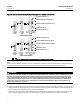
Avoid damaging the seating surface caused by the valve plug and stem assembly dropping from the bonnet (key 1, figure
14) after being lifted part way out. When lifting the bonnet, temporarily install a valve stem locknut on the valve stem. The
locknut will prevent the valve plug and stem assembly from dropping out of the bonnet.
4. Hex nuts (key 16, figure 16, 17, or 20) or cap screws (not shown) attach the bonnet (key 1, figure 14) to the valve
body (key 1, figure 16, 17, or 20). Loosen these nuts or cap screws approximately 3 mm (1/8 inch). Then loosen the
body-to-bonnet gasketed joint by either rocking the bonnet or prying between the bonnet and valve. Work the