
Data Sheet

ET Valve
D100022X012
Product Bulletin
51.1:ET
December 2012
24
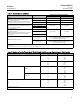
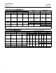
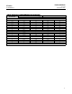
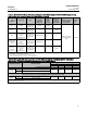
Table 19. Fisher ET and ETR Dimensions
VALVE
SIZE, NPS
A G(MAX)
Pressure Rating, End Connection Style
(1)
Scrd or
SW
CL125 FF
or
CL150 RF
CL150
RTJ
CL250 RF
or
CL300 RF
CL300
RTJ
BW or
CL600 RF
CL600
RTJ
PN16-40
(
2)
PN63-100
(2)
ET ETR
mm
1
1-1/2
2
210
251
286
184
222
254
197
235
267
197
235
267
210
248
282
210
251
286
210
251
289
160
200
230
230
260
300
60
71
78
119
116
133
2-1/2
3
4
6
8
---
---
---
---
---
276
298
353
451
543
292
311
365
464
556
292
317
368
473
568
308
333
384
489
584
311
337
394
508
610
314
340
397
511
613
290
310
350
480
600
340
380
430
550
650
90
97
129
140
191
159
168
192
---
---
Inch
1
1-1/2
2
8.25
9.88
11.25
7.25
8.75
10.00
7.75
9.25
10.50
7.75
9.25
10.50
8.25
9.75
11.12
8.25
9.88
11.25
8.25
9.88
11.38
See
mm
above
See
mm
above
2.38
2.81
3.06
4.69
4.56
5.25
2-1/2
3
4
6
8
---
---
---
---
---
10.88
11.75
13.88
17.75
21.38
11.38
12.25
14.38
18.25
21.88
11.50
12.50
14.50
18.62
22.38
12.12
13.12
15.12
19.25
23.00
12.25
13.25
15.50
20.00
24.00
12.38
13.38
15.62
20.12
24.12
3.56
3.81
5.06
5.51
7.50
6.25
6.62
7.56
---
---
1. End connection style abbreviations: BW - Buttwelding, FF - Flat Faced, Scrd - Screwed, SW - Socketweld, RF - Raised Face, R TJ - Ring Type Joint
2. Valves which meet EN 1092 flange standards and have EN face-to-face dimensions are available only from Europe (EN 558-1). Valves which meet EN 1092 flange standards but not EN
face-to-face standards are available in the US. Consult your Emerson Process Management sales office.
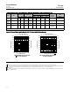
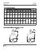
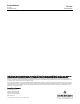
Figure 15. Fisher ET and ETR Dimensions (also see tables 19, 20, and 21)
2. For dimensions of valves with other end connections, consult your Emerson sales office.
A
G
D
MATCH LINE
FOR
ACTUATOR
1
1
B
AR4967-a
A0925-3
Notes:
B =
A
2
ET CONTROL VALVE
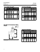
B
A
G
D
MATCH
LINE
FOR
ACTUATOR
1
10A7397-B
A0926-2
ETR CONTROL VALVE