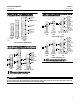
Instruction Manual ES Valve D100397X012 October 2014 Fisherr ES and EAS easy-et Valves CL125 through CL600 Contents Introduction . . . . . . . . . . . . . . . . . . . . . . . . . . . . . . . . . 1 Scope of Manual . . . . . . . . . . . . . . . . . . . . . . . . . . . . . 1 Description . . . . . . . . . . . . . . . . . . . . . . . . . . . . . . . . . 2 Specifications . . . . . . . . . . . . . . . . . . . . . . . . . . . . . . . 2 Installation . . . . . . . . . . . . . . . . . . . . . . . . . . . . . . . .
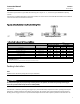
Instruction Manual ES Valve D100397X012 October 2014 Table 1. Specifications End Connection Styles Cast Iron Valves Flanged: CL125 flat-face or CL250 raised-face flanges per ASME B16.1 Steel and Stainless Steel Valves Flanged: CL150, 300, and 600 raised-face or ring-type joint flanges per ASME B16.5 Screwed or Socket Welding: All available ASME B16.11 schedules that are consistent with CL600 per ASME B16.34 Buttwelding: Consistent with ASME B16.
Instruction Manual ES Valve D100397X012 October 2014 Check with your process or safety engineer for any additional measures that must be taken to protect against process media. If installing into an existing application, also refer to the WARNING at the beginning of the Maintenance section in this instruction manual. Table 2.
ES Valve October 2014 Instruction Manual D100397X012 Valves with ENVIRO-SEAL live-loaded packing or HIGH-SEAL Heavy-Duty live-loaded packing will not require this initial re-adjustment. See the Fisher instruction manuals titled ENVIRO-SEAL Packing System for Sliding-Stem Valves or Heavy-Duty Live-Loaded Packing System (as appropriate) for packing instructions.
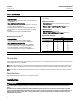
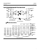
Instruction Manual ES Valve D100397X012 October 2014 instructions. Figure 9 shows a typical HIGH-SEAL Packing system. Figures 10, 11, and 12 show typical ENVIRO-SEAL packing systems. If the valve has an ENVIRO-SEAL bellows seal bonnet installed, refer to this manual. See the ENVIRO-SEAL Bellows Seal and Bonnet section for information on the bellows seal bonnet. Figure 2. Optional Lubricator and Lubricator/Isolating Valve 10A9421-A AJ5428-D A0832-2 LUBRICATOR LUBRICATOR/ISOLATING VALVE Table 3.
ES Valve Instruction Manual October 2014 D100397X012 operate the lubricator, simply turn the cap screw clockwise to force the lubricant into the packing box. The lubricator/isolating valve operates the same way except the isolating valve must first be opened and then closed after lubrication is completed. Packing Maintenance Key numbers refer to figure 3 for PTFE V-ring packing and to figure 5 for PTFE/composition packing, unless otherwise indicated.
Instruction Manual ES Valve D100397X012 October 2014 Figure 3.
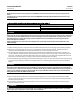
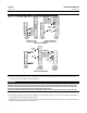
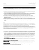
Instruction Manual ES Valve D100397X012 October 2014 Figure 4. PTFE Packing Arrangements for Use in ENVIRO-SEAL Bellows Seal Bonnets UPPER WIPER (KEY 12) BUSHING (KEY 13) PACKING SET: (KEY 6) FEMALE ADAPTOR PACKING RING MALE ADAPTOR SPACER (KEY 8) THRUST RING (KEY 39) 12B4182-A SHT 1 SPRING (KEY 8) THRUST RING (KEY 39) SPACER (KEY 8) 12B4185-A SHT 1 9.5 mm 12.7 mm (3/8 INCH) (1/2 INCH) STEM STEM FOR S31600 (316 SST) PACKING BOX PARTS 12B4185-A SHT 2 12B4182-A SHT 2 12.7 mm 9.
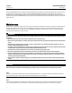
Instruction Manual ES Valve D100397X012 October 2014 Figure 5. Detail of PTFE/Composition Packing Arrangements for Plain and Extension Bonnets Figure 7. Detail of Graphite Ribbon/Filament Packing for Plain and Extension Bonnets PACKING FOLLOWER (KEY 13) UPPER WIPER (KEY 12) GRAPHITE RIBBON PACKING RING (KEY 7) PACKING FOLLOWER (KEY 13) 1 1 PACKING RING (KEY 7) 1 LANTERN RING (KEY 8) 14A3411-A 9.5 mm 12.
ES Valve October 2014 Instruction Manual D100397X012 CAUTION To prevent possible product damage, cover the opening in the valve in the following procedure to prevent foreign material from getting into the valve body cavity. 7. Remove the bonnet gasket (key 10, figure 13 through 15) and cover the opening in the valve to protect the gasket surface and prevent foreign material from getting into the valve body cavity. 8.
Instruction Manual ES Valve D100397X012 October 2014 15. Mount the actuator on the valve assembly and reconnect the actuator and valve stem according to the procedure in the appropriate actuator instruction manual. Trim Maintenance WARNING Refer to the WARNING at the beginning of the Maintenance section in this instruction manual. CAUTION In the following applicable procedures, to avoid damaging parts, do not grip the bellows shroud or other parts of the stem/bellows assembly.
Instruction Manual ES Valve D100397X012 October 2014 WARNING To avoid personal injury due to leaking fluid, avoid damaging gasket sealing surfaces. The surface finish of the valve stem (key 7) is critical for making a good packing seal. The inside surface of the cage or cage/baffle assembly (key 3), or cage retainer (key 31), is critical for smooth operation of the valve plug. The seating surfaces of the valve plug (key 2) and seat ring (key 9) are critical for proper shutoff.
Instruction Manual D100397X012 ES Valve October 2014 Lapping Metal Seats A certain amount of leakage should be expected with metal-to-metal seating in any valve body. If the leakage becomes excessive, however, the condition of the seating surfaces of the valve plug and seat ring can be improved by lapping. (Deep nicks should be machined out rather than ground out.) Use a good quality lapping compound of a mixture of 280 to 600-grit. Apply the compound to the bottom of the valve plug.
Instruction Manual ES Valve D100397X012 October 2014 up. The level D3 cage/baffle assembly, however, must be installed with the hole pattern end next to the seat ring. If a cage retainer (key 31) is to be used, place it on top of the cage. 4. Slide the valve plug (key 2) and stem assembly, or valve plug and ENVIRO-SEAL bellows seal assembly, into the cage. 5. Place the gaskets (key 10, or keys 11, 12 and 14, if used) and the shim (key 27 or key 51) on top of the cage or cage retainer.
Instruction Manual D100397X012 ES Valve October 2014 4. Inspect the existing valve plug. If the plug is in good condition, it can be reused with the new ENVIRO-SEAL stem/bellows assembly. To remove the existing valve plug from the stem, first, place the existing plug stem assembly and valve plug in a soft-jaw chuck or other type of vise so that the jaws grip a portion of the valve plug that is not a seating surface. Drive out or drill out the pin (key 8). 5.
ES Valve Instruction Manual October 2014 D100397X012 mark visible. Contact your Emerson Process Management representative immediately if a discrepancy between actual parts and approved parts is suspected. 12. Properly lubricate the bonnet stud bolts. Install and tighten the bonnet hex nuts to the proper torque. 13. Install new packing and the metal packing box parts according to the appropriate arrangement in figure 3. 14. Install the packing flange.
Instruction Manual D100397X012 ES Valve October 2014 Note The ENVIRO-SEAL stem/bellows assembly has a one-piece stem. 4. To remove the existing valve plug from the stem, first, place the existing plug stem assembly and valve plug in a soft-jaw chuck or other type of vise so that the jaws grip a portion of the valve plug that is not a seating surface. Drive out or drill out the pin. 5. Then, reverse the plug stem assembly in the soft-jaw chuck or vise.
Instruction Manual ES Valve D100397X012 October 2014 Gasket Kits Gasket Kits (includes keys 10, 11, 12, 13, and 51); plus 14 and 20 on Some Restricted Capacity Valves DESCRIPTION Standard Trim Cage Whisper Trim I Cage -198 to 593_C (-325 to 1100_F) Full Capacity Valves NPS 1/2, 3/4, 1, and 1-1/4 (NPS 1 EAS) NPS 1-1/2 (NPS 2 EAS) NPS 2 NPS 2-1/2 (NPS 3 EAS) NPS 3 (NPS 4 EAS) NPS 4 (NPS 6 EAS) NPS 6 NPS 8 Whisper Trim III Cage WhisperFlo Cage -198 to 593_C (-325 to 1100_F) Part Number Part Number RG
Instruction Manual ES Valve D100397X012 October 2014 ENVIRO-SEAL Packing Retrofit Kits PACKING MATERIAL STEM DIAMETER AND YOKE BOSS DIAMETER, mm (INCH) 9.5 (3/8) 54 (2-1/8) 12.7 (1/2) 71 (2-13/16) 19.1 (3/4) 90 (3-9/16) 25.4 (1) 127 (5) 31.
Instruction Manual ES Valve D100397X012 October 2014 Key 8 8 8 8 10 11* 12* 12* 13* 13* 13* 20 Description and NPS 2 with 12.7 mm (1/2 inch) stem (4 req'd) Filament packing ring for 9.5 mm (3/8 inch) and NPS 2 with 12.7 mm (1/2 inch) stem (4 req'd) Ribbon packing ring for NPS 3 and 4 with 12.7 mm (1/2 inch) stem (4 req'd) Filament packing ring for NPS 3 and 4 with 12.
Instruction Manual ES Valve D100397X012 October 2014 Figure 8.
Instruction Manual ES Valve D100397X012 October 2014 Figure 9. Typical HIGH-SEAL Graphite ULF Packing System Figure 11. Typical ENVIRO-SEAL Packing System with Graphite ULF Packing STUD (KEY 200) HEX NUT (KEY 212) PACKING FLANGE (KEY 201) PACKING RING (KEY 209) PACKING RING (KEY 210) PACKING BOX RING (KEY 211) 1. FIND NUMBER 219 NOT REQUIRED WITH 3/8 INCH STEM SPRING PACK ASSEMBLY (KEY 217) GUIDE BUSHING (KEY 207) PACKING WASHERS (KEY 214) GUIDE BUSHING (KEY 208) 39B4612/A 39B4153-A Figure 10.
Instruction Manual ES Valve D100397X012 October 2014 Keys 6*, 7*, 8, and 10 Packing Box Parts(1) PTFE V-Ring Packing 9.5 (3/8) 12.7 (1/2) 19.1 (3/4) 25.4 (1) 31.
Instruction Manual ES Valve D100397X012 October 2014 Figure 13.
Instruction Manual ES Valve D100397X012 October 2014 Figure 14.
ES Valve October 2014 Figure 15.
Instruction Manual ES Valve D100397X012 October 2014 Figure 16.
Instruction Manual ES Valve D100397X012 October 2014 Keys 2*, 7*, and 8* Valve Plug and Stem Assembly for Plain Bonnet VALVE SIZE, NPS ES 1/2 thru 2 1/2 thru 2 ORIFICE SIZE EAS 1, 2 1, 2 STEM DIA & VSC SIZE 13Cr 400-Series Stainless Steel 316 Stainless Steel(1) 316 Stainless Steel w/ CoCr-A on Seat(1) 316 Stainless Steel w/ CoCr-A on Seat & Guide(1) HIGH TEMPERATURE(2) Inch mm Inch 6.4 0.25 9.
Instruction Manual ES Valve D100397X012 October 2014 Keys 2*, 7*, and 8* Valve Plug and Stem Assembly for Style 1 Extension Bonnet VALVE SIZE, NPS ES 1/2 thru 2 1/2 thru 2 ORIFICE SIZE EAS 1, 2 1, 2 STEM DIA & VSC SIZE 13Cr 400-Series Stainless Steel 316 Stainless Steel(1) 316 Stainless Steel w/ CoCr-A on Seat(1) 316 Stainless Steel w/ CoCr-A on Seat & Guide(1) HIGH TEMPERATURE(2) Inch mm Inch 6.4 0.25 9.
Instruction Manual ES Valve D100397X012 October 2014 Keys 2* Valve Plug VALVE SIZE, NPS ES ORIFICE SIZE EAS 1/2 thru 2 1, 2 STEM DIA & VSC SIZE 13Cr 400-Series Stainless Steel 316 Stainless Steel(1) 316 Stainless Steel w/ CoCr-A on Seat(1) 316 Stainless Steel w/ CoCr-A on Seat & Guide(1) HIGH TEMPERATURE(2) mm Inch mm Inch 6.4 0.25 9.5 3/8 1U288546172 1U288535072 2U854946052 2V364046062 316 Stainless Steel w/ CoCr-A on Seat & Guide 21A8444X012 9.5 0.375 9.
Instruction Manual ES Valve D100397X012 October 2014 Key 3* Linear Cage VALVE SIZE, NPS ES EAS 1, 1-1/4, 1-1/2 x 1, or 2 x 1 1-1/2 or 2-1/2 x 1-1/2 2 or 3 x 2 2-1/2 or 4 x 2-1/2 3 4 6 8 1 or 2 x 1 2 or 3 x 1-1/2 4x2 3 or 6 x 2-1/2 4 6 ----- 316 SST 17-4PH SST (HARDENED) Chrome Plated Nickel Coated ALLOY 6 2U215633272 2U219833272 2U224033272 2U228233272 2U232433272 2U236633272 2U506133272 20A3247X012 2U691746102 2U692046102 2U692346102 2U692646102 2U692946102 2U693346102 2U693846102 20A4349X012
Instruction Manual ES Valve D100397X012 October 2014 Key 7* Fisher ES Valve Plug Stem, 316 stainless steel (not for Whisper Trim III cage) VALVE SIZE, NPS Full Capacity Restricted Capacity PLAIN BONNET(3) STEM DIA & VSC SIZE Stem Length Part Number EXTENSION BONNET Style 1(3) Stem Length Style 2 Stem Length mm Inches Part Number 1U388835162 1U389035162 311 402 12.25 15.8125 1U217735162 1U217935162 405 473 15.9375 18.625 10A8823X022 1U218035162 12.25 14.
Instruction Manual ES Valve D100397X012 October 2014 Key 7* Fisher EAS Valve Plug Stem for Plain and Extension Bonnets Stem Length EXTENSION BONNET Part Number Style 1 Stem Length Style 2 Stem Length mm Inches Part Number 1U388835162 1U389035162 311 402 12.25 15.8125 1U217735162 1U217935162 405 473 15.9375 18.625 1U217835162 1U218035162 12.625 15 1U230535162 1U230835162 421 502 16.5625 19.75 1U230635162 1U444635162 624 --- 24.5625 --- 1U230735162 --- 321 394 464 489 12.625 15.
Instruction Manual ES Valve D100397X012 October 2014 Key 9* Fisher EAS Liner Liner Material Valve Size, NPS CL150 Raised Face CL300 Raised Face CL600 Raised Face Socket Weld 416 SST (hardened) 1 2 2x1 3 3 x 1-1/2 4 4x2 6 6 x 2-1/2 1V560146172 1V560346172 1V560646172 2V561346172 2V560946172 2V562246172 2V561846172 2V563146172 2V562646172 1U384246172 1U384346172 1U385146172 2U384546172 2U385346172 2U384746172 2U385546172 2U384946172 2U385746172 1V560246172 1V560546172 1V387646172 2V561646172 2V5
Instruction Manual ES Valve D100397X012 October 2014 Gasket Descriptions MATERIAL KEY NUMBER DESCRIPTION 10 Bonnet Gasket FGM -198_ to 593_C (-325_ to 1100_F) 11 Cage Gasket 13 Seat Ring or Liner Gasket Graphite/S31600 14 or 20 Adapter Gasket 12 Spiral Wound Gasket N06600/Graphite 27 or 51 Shim S31600 Keys 10*, 11*, 12*, 13*, 14*, 20*, 27*, and 51* Gaskets and Shims Valve Size, NPS ES 1/2, 3/4, 1 or 1-1/4 1-1/2 1-1/2 x 1 2 2x1 2-1/2 Standard Trim Cage Whisper Trim I Cage Whisper
Instruction Manual ES Valve D100397X012 October 2014 Keys 21*, 22*, and 23* PTFE-Seat Disk Retainer, Disk Seat, and Disk VALVE SIZE, NPS ES EAS KEY 21 DISK RETAINER, 316 SST 1V710035072 316 SST CoCr-A 1V710235072 1V710239012 KEY 23 DISK, PTFE -73_ TO 204_C (-100_ TO 400_F) 1V710106242 1V710539102 1V712239102 1V710639102 1V711139102 1V711439102 1V711739102 1V7120X0012 1V710406242 1V710106242 1V710706242 1V711006242 1V711306242 1V711606242 1V711906242 KEY 22 DISK SEAT 1/2, 3/4, 1, 1-1/4, or 2 x