
Quick Start Guide


Quick Start Guide
D103470X012
DLC3020f Digital Level Controller
July 2012
19
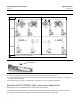
GUIDED SETUP
INSTRUMENT SETUP
CONFIGURE
Figure 10. Guided Setup
Manual Setup
AMS Device Manager Configure > Manual Setup
Field Communicator Configure > Manual Setup
The Device, Process Fluid, Instrument Display, Snap Acting Control, and Options tabs are accessible through Manual Setup.
Note
An error will be generated if the instrument is put back in service without applying device configuration changes; you must apply
changes before putting the instrument back In Service. To clear an error, set the Mode to Out of Service, select Apply, then put
back In Service.
Device
Select the Device tab (figure 11) to access Variable Configuration, Sensor Limits, Sensor Hardware Information, Sensor
Units, Mode, Sensor Parameters, Instrument Mount Position, and Torque Tube.
Variable Configuration
Type of Measurement— Level or Interface
Primary Value Range High— defines the maximum operational end point for reported PV.
Primary Value Range Low— defines the minimum operational end point for reported PV. Default is above zero.