
Quick Start Guide


Quick Start Guide
D103470X012
DLC3020f Digital Level Controller
July 2012
14
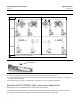
6. Carefully slide the digital level controller with the attached insulator over the shaft coupling so that the access hole
is on the bottom of the digital level controller.
7. Secure the digital level controller and insulator to the torque tube arm with four cap screws.
8. Tighten the cap screws to 10 NSm (88.5 lbfSin).
Electrical Connections
The following describes how to make fieldbus connections to the digital level controller.
WARNING
To avoid personal injury resulting from electrical shock, do not exceed the maximum input voltage specified in table 8 or on
the product nameplate. If the input voltage specified differs, do not exceed the lowest specified maximum input voltage.
WARNING
Select wiring and/or cable glands that are rated for the environment of use (such as hazardous area, ingress protection and
temperature). Failure to use properly rated wiring and/or cable glands can result in personal injury or property damage
from fire or explosion
Wiring connections must be in accordance with local, regional, and national codes for any given hazardous area approval.
Failure to follow the local, regional, and national codes could result in personal injury or property damage from fire or
explosion.
Personal injury or property damage caused by fire or explosion may occur if this connection is attempted in a potentially
explosive atmosphere or in an area that has been classified as hazardous. Confirm that area classification and atmosphere
conditions permit the safe removal of the terminal box cover before proceeding
Fieldbus Connections
The digital level controller is normally powered over the bus from a fieldbus 9 to 32 volt power supply and can be
connected to the segment using field wiring. Refer to the site preparation guide for proper wire types, termination,
length, etc. for a fieldbus segment.
Note
As shipped from the factory, the DLC3020f will have the transducer block mode set Out of Service. See the Configuration section
for information on setup and calibration and placing the instrument in service. The initial value for all blocks are shown in the
parameter list for each block in the Blocks section.