
Quick Start Guide


Quick Start Guide
D103470X012
DLC3020f Digital Level Controller
July 2012
13
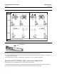
HEAT INSULATOR
REQUIRED
70
0 20 40 60 80 100 120 140 160
010 20
-20 -10
30 40 50 60
400
300
200
100
0
0
400
800
-325
AMBIENT TEMPERATURE (_C)
STANDARD TRANSMITTER
AMBIENT TEMPERATURE (_F)
HEAT INSULATOR
REQUIRED
TOO
HOT
NOTES:
FOR PROCESS TEMPERATURES BELOW -29_C (-20_F) AND ABOVE 204_C (400_F) SENSOR MATERIALS
MUST BE APPROPRIATE FOR THE PROCESS - SEE TABLE 9.
2. IF AMBIENT DEW POINT IS ABOVE PROCESS TEMPERATURE, ICE FORMATION MIGHT CAUSE INSTRUMENT
MALFUNCTION AND REDUCE INSULATOR EFFECTIVENESS.
39A4070‐B
A5494‐1
425
80
-100
-200
176
-20-40
-40 -30
TOO
COLD
1
1
NO HEAT INSULATOR NECESSARY
Figure 6. Guidelines for Use of Optional Heat Insulator Assembly
PROCESS TEMPERATURE (_F)
PROCESS TEMPERATURE (_C)
CAUTION
Measurement errors can occur if the torque tube assembly is bent or misaligned during installation.
1. When mounting a DLC3020f on a 249 sensor, secure the shaft extension to the sensor torque tube shaft via the
shaft coupling and set screws, with the coupling centered as shown in figure 7.
2. Slide the access handle to the locked position to expose the access hole. Press on the back of the handle as shown in
figure 2 then slide the handle toward the front of the unit. Be sure the locking handle drops into the detent.
MN28800
20A7423‐C
B2707
SENSOR
DIGITAL LEVEL CONTROLLER
SHAFT
EXTENSION
(KEY 58)
SHAFT
COUPLING
(KEY 59)
SET SCREWS
(KEY 60)
INSULATOR
(KEY 57)
CAP SCREWS
(KEY 63)
MOUNTING STUDS
(KEY 33)
HEX NUTS
(KEY 34)
WASHER
(KEY 78)
Figure 7. Digital Level Controller Mounting on Sensor in High Temperature Applications
3. Remove the hex nuts from the mounting studs.
4. Position the insulator on the digital level controller, sliding the insulator straight over the mounting studs.
5. Install 4 washers (key 78) over the studs. Install the four hex nuts and tighten.