
Quick Start Guide


Quick Start Guide
D103470X012
DLC3020f Digital Level Controller
July 2012
12
8
2
4
6
3
7
1
5
SENSOR
CAGED
CAGELESS
RIGHT‐OF‐DISPLACER
LEFT‐OF‐DISPLACER
1 NOT AVAILABLE FOR SIZE NPS 2 CL300 AND CL600 249C SENSOR.
8
2
4
6
1
3
7
5
249VS
249W
249W
249VS
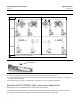
Figure 4. Typical Mounting Positions for the FIELDVUE DLC3020f Digital Level Controller on a Fisher 249 Sensor
1
1
SET‐SCREW (2mm)
Figure 5. Close‐up of Set‐Screw
4. Position the digital level controller so the access hole is on the bottom of the instrument.
5. Carefully slide the mounting studs into the sensor mounting holes until the digital level controller is snug against
the sensor mounting flange.
6. Reinstall the hex nuts on the mounting studs and tighten the hex nuts to 10 NSm (88.5 lbfSin).
Mounting the DLC3020f for High Temperature Applications
Refer to figure 7 for parts identification except where otherwise indicated.
The digital level controller requires an insulator assembly when temperatures exceed the limits shown in figure 6.
A torque tube shaft extension is required for a 249 sensor when using an insulator assembly.