Quick Start Guide DLC3020f Digital Level Controller D103470X012 July 2012 Fisherr FIELDVUE™ DLC3020f Digital Level Controller for FOUNDATION™ fieldbus Contents Installation . . . . . . . . . . . . . . . . . . . . . 3 Mounting . . . . . . . . . . . . . . . . . . . . . . 10 Electrical Connections . . . . . . . . . . . 14 Configuration . . . . . . . . . . . . . . . . . . 18 Calibration . . . . . . . . . . . . . . . . . . . . . 33 Nameplates and Schematics . . . . . . 37 Specifications . . . . . . . . . . .
DLC3020f Digital Level Controller Quick Start Guide D103470X012 July 2012 nInstallation Check List Mounting j Instrument correctly configured and mounted on the sensor. See the appropriate mounting procedure or installation instructions provided with the mounting kit. Wiring and Electrical Connections j Conduit or I.S. barrier, if necessary, properly installed. Refer to local and national electrical codes. j Loop wiring properly connected to the LOOP + and - terminals in the terminal box.
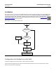
Quick Start Guide DLC3020f Digital Level Controller D103470X012 July 2012 Installation Do not install, operate, or maintain a DLC3020f digital level controller without being fully trained and qualified in field instrument and accessory installation, operation, and maintenance. To avoid personal injury or property damage, it is important to carefully read, understand, and follow all of the contents of this manual, including all safety cautions and warnings.
Quick Start Guide DLC3020f Digital Level Controller D103470X012 July 2012 Protecting the Coupling and Flexures CAUTION Damage to flexures and other parts can cause measurement errors. Observe the following steps before moving the sensor and controller. Lever Lock The lever lock is built in to the coupling access door. When the door is open, it positions the lever in the neutral travel position for coupling.
Quick Start Guide DLC3020f Digital Level Controller D103470X012 July 2012 2. If the displacer cannot be blocked because of cage configuration or other concerns, the transmitter is uncoupled from the torque tube by loosening the coupling nut, and the access handle will be in the locked position. Before placing such a configuration into service, couple the instrument to the sensor as follows: a. Slide the access handle to the open position to lock the lever assembly in place and expose the access hole.
Quick Start Guide DLC3020f Digital Level Controller D103470X012 July 2012 Hazardous Area Classifications and Special Instructions for “Safe Use” and Installation in Hazardous Locations Certain nameplates may carry more than one approval, and each approval may have unique installation/wiring requirements and/or conditions of “safe use”. These special instructions for “safe use” are in addition to, and may override, the standard installation procedures. Special instructions are listed by approval.
Quick Start Guide DLC3020f Digital Level Controller D103470X012 July 2012 FM Intrinsically Safe, Explosion‐proof, Non-Incendive, Dust Ignition‐proof No special conditions for safe use. Refer to table 2 for approval information, figure 24 for the FM schematic, and figure 23 for a typical CSA/FM nameplate. Table 2.
Quick Start Guide DLC3020f Digital Level Controller D103470X012 July 2012 ATEX Special Conditions for Safe Use Intrinsically Safe & Dust This apparatus can only be connected to an intrinsically safe certified equipment and this combination must be compatible regarding the intrinsic safety rules (see electrical parameters in table 3). Flameproof & Dust, Type n & Dust No special conditions for safe use. Refer to table 3 for additional approval information and figure 26 for a typical ATEX/IECEx nameplate.
Quick Start Guide DLC3020f Digital Level Controller D103470X012 July 2012 IECEx Conditions of Certification Intrinsically Safe & Dust This apparatus shall only be connected to an intrinsically safe certified equipment and this combination must be compatible regarding the intrinsic safety rules (see electrical parameters in table 4). Flameproof & Dust, Type n & Dust No conditions of certification. Refer to table 4 for additional approval information, and figure 26 for a typical ATEX/IECEx nameplate.
Quick Start Guide DLC3020f Digital Level Controller D103470X012 July 2012 Mounting WARNING To avoid personal injury or property damage, always wear protective gloves, clothing, and eyewear when performing any installation operations. Personal injury or property damage due to sudden release of pressure, contact with hazardous fluid, fire, or explosion can be caused by puncturing, heating, or repairing a displacer that is retaining process pressure or fluid.
Quick Start Guide DLC3020f Digital Level Controller D103470X012 July 2012 The DLC3020f digital level controller is typically shipped attached to the sensor. If ordered separately, it may be convenient to mount the digital level controller to the sensor and perform the initial setup and calibration before installing the sensor on the vessel. Note Caged sensors have a rod and block installed on each end of the displacer to protect the displacer in shipping.
Quick Start Guide DLC3020f Digital Level Controller D103470X012 July 2012 Figure 4. Typical Mounting Positions for the FIELDVUE DLC3020f Digital Level Controller on a Fisher 249 Sensor SENSOR LEFT‐OF‐DISPLACER 1 5 7 6 RIGHT‐OF‐DISPLACER 8 1 3 CAGED 3 1 5 4 2 1 4 2 8 7 6 CAGELESS 249VS 1 249W 249W 249VS NOT AVAILABLE FOR SIZE NPS 2 CL300 AND CL600 249C SENSOR. Figure 5. Close‐up of Set‐Screw SET‐SCREW (2mm) 4.
Quick Start Guide DLC3020f Digital Level Controller D103470X012 July 2012 PROCESS TEMPERATURE (_F) AMBIENT TEMPERATURE (_C) -40 800 -30 -20 -10 0 10 20 30 40 50 60 80 TOO HOT HEAT INSULATOR REQUIRED 400 70 425 400 300 200 100 -325 -40 0 NO HEAT INSULATOR NECESSARY 0 1 -100 TOO COLD -20 HEAT INSULATOR REQUIRED 0 20 40 60 -200 80 100 120 140 160 176 PROCESS TEMPERATURE (_C) Figure 6.
DLC3020f Digital Level Controller July 2012 Quick Start Guide D103470X012 6. Carefully slide the digital level controller with the attached insulator over the shaft coupling so that the access hole is on the bottom of the digital level controller. 7. Secure the digital level controller and insulator to the torque tube arm with four cap screws. 8. Tighten the cap screws to 10 NSm (88.5 lbfSin). Electrical Connections The following describes how to make fieldbus connections to the digital level controller.
Quick Start Guide DLC3020f Digital Level Controller D103470X012 July 2012 1. Remove the terminal box cover (key 6) from the terminal box (key 5). 2. Bring the field wiring into the terminal box. When applicable, install conduit using local and national electrical codes which apply to the application. 3. Connect one wire from the control system output card to the LOOP + terminal in the terminal box as shown in figure 8. Connect the other wire from the control system output card to the LOOP - terminal.
DLC3020f Digital Level Controller July 2012 Quick Start Guide D103470X012 Communication Connections WARNING Personal injury or property damage caused by fire or explosion may occur if this connection is attempted in a potentially explosive atmosphere or in an area that has been classified as hazardous. Confirm that area classification and atmosphere conditions permit the safe removal of the terminal box cap before proceeding.
Quick Start Guide DLC3020f Digital Level Controller D103470X012 July 2012 nConfiguration and Calibration Check List j Configuration and Calibration complete. j Configuration check. Confirm all final process data is correctly entered. j j Transmitter correctly reports PV. Ensure Setup Calibration log is saved. Transmitter is ready to be placed on line.
DLC3020f Digital Level Controller Quick Start Guide D103470X012 July 2012 Configuration Note This quick start guide documents procedures in AMS Device Manager 10.5 and later. Earlier versions of AMS Device Manager contain the same procedures and methods, but access is through the block in which they reside. Note The primary transducer block must be set to out of service before the device can be configured. When using AMS Device Manager 10.
Quick Start Guide DLC3020f Digital Level Controller D103470X012 July 2012 Figure 10. Guided Setup GUIDED SETUP INSTRUMENT SETUP CONFIGURE Manual Setup AMS Device Manager Configure > Manual Setup Field Communicator Configure > Manual Setup The Device, Process Fluid, Instrument Display, Snap Acting Control, and Options tabs are accessible through Manual Setup.
Quick Start Guide DLC3020f Digital Level Controller D103470X012 July 2012 Figure 11. Configure > Manual Setup > Device DEVICE TAB VARIABLE CONFIGURATION SELECT UNIT SYSTEM SENSOR PARAMETERS MANUAL SETUP SENSOR LIMITS CONFIGURE SENSOR HARDWARE INFORMATION TORQUE TUBE INSTRUMENT MOUNT POSITION Primary Value Offset— the constant offset applied to the level/interface measurement. Primary Value Range Units— units for PV, PV Range, and Sensor Limits.
Quick Start Guide DLC3020f Digital Level Controller D103470X012 July 2012 Sensor Units Select the appropriate sensor units for your application. Note Default units from factory are SI (Metric). If you choose Mixed Units you must select the units for each sensor parameter. Figure 12.
Quick Start Guide DLC3020f Digital Level Controller D103470X012 July 2012 Note Table 5 provides the driver rod length of 249 sensors with vertical displacers. If your sensor isn't included in table 5 refer to figure 13 to determine the driver rod length. Table 5. Driver Rod Length(1) Driver Rod Sensor Type(2) mm Inch 249 203 8.01 249B 203 8.01 249BF(3) 203 8.01 249BP 203 8.01 249C 169 6.64 249CP 169 6.64 249K 267 10.5 249L 229 9.01 249N 267 10.
Quick Start Guide DLC3020f Digital Level Controller D103470X012 July 2012 Figure 13. Method of Determining Driver Rod Length from External Measurements VERTICAL CL OF DISPLACER VESSEL HORIZONTAL CL OF TORQUE TUBE DISPLACER ROD LENGTH Torque Tube Torque Tube Material—select the material of the torque tube being used. See the sensor nameplate. View Torque Tube Table—select View Torque Tube Table to see the torque tube gain over the entire temperature range and the compensated torque rate.
Quick Start Guide DLC3020f Digital Level Controller D103470X012 July 2012 Process Fluid Select the Process Fluid tab (figure 14) to access Process Fluid, Temperature Compensation, and Mode. Figure 14. Configure > Manual Setup > Process Fluid MANUAL SETUP CONFIGURE PROCESS FLUID TAB PROCESS FLUID CHANGE PROCESS FLUID TEMPERATURE COMPENSATION MODE VIEW DENSITY PARAMETERS Note The instrument software contains density tables for common categories of fluids. Custom tables can be built if needed.
Quick Start Guide DLC3020f Digital Level Controller D103470X012 July 2012 Temperature Compensation If Temperature Compensation is selected, provide the following information: Temperature Input—select None, Manual, AO Block, or RTD. Temperature compensation, when enabled, can come from a manually entered temperature, a temperature from a fieldbus transmitter (AO block) or a temperature from an RTD.
Quick Start Guide DLC3020f Digital Level Controller D103470X012 July 2012 Decimal Places Enter the number of desired decimal places for the device display. Display Primary Value Offset Enter the PV Offset to apply it to the LCD readout. Scrolling Message Control Messages that can be scrolled on the LCD screen. Choose from; Primary Value Bad, Primary Value Uncertain, Failed Alert, Maintenance Alert, or Advisory Alert.
Quick Start Guide DLC3020f Digital Level Controller D103470X012 July 2012 Primary Value PV in engineering units Primary Value Percent PV in % DI1 Trip Point Settings Set Channel 1 or 2 of the DI for snap acting control. DI1 Action—indicate whether the trip point is active on rising or falling level. DI1 Trip Point—enter the point where DI1 is active. DI1 Deadband—enter the desired deadband. This is the distance away from the trip point that DI1 clears.
Quick Start Guide DLC3020f Digital Level Controller D103470X012 July 2012 Figure 17. Configure > Manual Setup > Options WRITE ALARM MANUAL SETUP COMMUNICATION TIMEOUT CONFIRM TIME OPTIONS TAB MODE FUNCTION BLOCK AVAILABLE ALERT KEY MAXIMUM ALERTS ALLOWED MAXIMUM ALERTS POSSIBLE BOCK ALARM RESOURCE BLOCK TRANSDUCER BLOCK CONFIGURE WRITE LOCK FEATURES SELECTED Alarm State—indicates the state of the Write Alarm.
Quick Start Guide D103470X012 DLC3020f Digital Level Controller July 2012 Confirm Time Confirm Time determines the time in 1/32 of a millisecond, the instrument waits for confirmation of receipt of a report before trying again. If Confirm Time is 0, the instrument does not try to resend the report. Enter 0 or a value between 320000 (10 seconds) and 640000 (20 seconds).
DLC3020f Digital Level Controller Quick Start Guide D103470X012 July 2012 Features Selected Note Typically this parameter does not need to be changed. The unit will be operational using the default values assigned by the factory. Features Selected indicates which Resource Block Options features have been selected and is used to select the desired features. Reports—Selecting reports enables alert and event reporting. Reporting of specific alerts may be suppressed.
Quick Start Guide DLC3020f Digital Level Controller D103470X012 July 2012 Figure 18. Alert Setup ALERT SETUP ALERT SETUP TAB ELECTRONICS OPERATIONAL RATE LIMIT SCROLL DOWN TO VIEW: SENSOR BOARD TEMPERATURE LIMIT INPUT COMPENSATION ERROR CONFIGURE Alerts The DLC3020f provides two levels of alerts; Instrument alerts and PlantWeb alerts. Instrument Alert Conditions Instrument Alert Conditions, when enabled, detect many operational and performance issues that may be of interest.
DLC3020f Digital Level Controller Quick Start Guide July 2012 D103470X012 Maintenance— indicates a problem with the DLC3020f that, if ignored, could eventually lead to its failure. Maintenance conditions require prompt action. Advisory— indicates a minor problem with the DLC3020f. An advisory condition does not have an impact on the process or device. No Category— the alert has not been categorized.
Quick Start Guide DLC3020f Digital Level Controller D103470X012 July 2012 D Hall Sensor— when selected indicates if the Hall Sensor readings are out of range. Temperature Limit D Instrument Temperature High— when selected indicates if the device has exceeded the Instrument Temperature High Limit. D Instrument Temperature Low— when selected indicates if the device has exceeded the Instrument Temperature Low Limit.
Quick Start Guide DLC3020f Digital Level Controller D103470X012 July 2012 Calibrate Instrument Choose Full Calibration (Bench) or Full Calibration (Field) and follow AMS Device Manager (or the Field Communicator or other host system) prompts to calibrate the instrument. Guided Calibration recommends an appropriate calibration procedure. Figure 19.
Quick Start Guide DLC3020f Digital Level Controller D103470X012 July 2012 Figure 20. Expert User Calibrations CALIBRATE EXPERT USER CALIBRATIONS TAB FULL CALIBRATION TRIM CURRENT CALIBRATION CONFIGURE Calibration Descriptions Full Calibration Weight (Bench only)—Weight Calibration is a bench calibration where weights are used to simulate the different forces the device sees at the minimum and maximum levels. All configuration data is needed to perform a Weight calibration.
DLC3020f Digital Level Controller July 2012 Quick Start Guide D103470X012 When complete, the torque rate or gain will be correct at the calibration temperature. After finalizing the installation a zero trim may be needed since a zero shift may take place when installing the device. Two Point (Bench or Field)—A Two Point Calibration fully calibrates the device by observing the level/interface at two points. The two points must be at least 5% of the displacer length apart.
Quick Start Guide DLC3020f Digital Level Controller D103470X012 July 2012 Schematics and Nameplates This section includes loop schematics required for wiring of intrinsically safe installations and typical approvals nameplates. If you have any questions, contact your Emerson Process Management sales office. Figure 21. CSA Schematic (Refer to figure 22 for Notes) HAZARDOUS LOCATION NON‐HAZARDOUS LOCATION I.S. CLASS I,II,III DIVISION 1, GROUPS A,B,C,D,E,F,G N.I.
DLC3020f Digital Level Controller July 2012 Quick Start Guide D103470X012 Figure 22. CSA Schematics (Notes) THE ENTITY CONCEPT ALLOWS INTERCONNECTION OF INTRINSICALLY SAFE APPARATUS TO ASSOCIATED APPARATUS NOT SPECIFICALLY EXAMINED IN SUCH COMBINATION.
Quick Start Guide DLC3020f Digital Level Controller D103470X012 July 2012 Figure 24. FM Schematic (Refer to figure 25 for Notes) HAZARDOUS LOCATION NON‐HAZARDOUS LOCATION I.S. CLASS I,II,III DIVISION 1, GROUPS A,B,C,D,E,F,G N.I. CLASS I, DIVISION 2, GROUPS A,B,C,D RTD DEVICE FM APPROVED ENTITY DEVICE NOTE 1, 3 DLC3020F MAIN CIRCUIT RTD TERMINALS TERMINALS Voc = 6.6 VDC Vmax ≤ 24 VDC Isc = 29.5 mA Imax ≤ 380 mA Po = 49 mW Pi ≤ 1.
DLC3020f Digital Level Controller Quick Start Guide July 2012 D103470X012 Figure 25. FM Schematics (Notes) THE ENTITY CONCEPT ALLOWS INTERCONNECTION OF INTRINSICALLY SAFE APPARATUS TO ASSOCIATED APPARATUS NOT SPECIFICALLY EXAMINED IN SUCH COMBINATION.
Quick Start Guide DLC3020f Digital Level Controller D103470X012 July 2012 Instrument Description The FIELDVUE DLC3020f digital level controller (figure 27) is a fieldbus communicating instrument used to measure liquid level or the level of interface between two liquids using displacement sensor technology. Figure 27.
DLC3020f Digital Level Controller Quick Start Guide July 2012 D103470X012 Related Documents Other documents containing information related to the DLC3020f digital level controllers and 249 sensors include: D Bulletin 11.2:DLC3020f - FIELDVUE DLC3020f Digital Level Controller (D103433X012) D Fisher FIELDVUE DLC3020f Digital Level Controller Instruction Manual (D103434X012) D Bulletin 34.
Quick Start Guide DLC3020f Digital Level Controller D103470X012 July 2012 Table 6. Specifications Block Execution Times AI, PID, DI, AO, ISEL: 15 ms ARTH: 25 ms Available Configurations Mounts on 249 caged and cageless sensors.
Quick Start Guide DLC3020f Digital Level Controller D103470X012 July 2012 Table 6.
Quick Start Guide DLC3020f Digital Level Controller D103470X012 July 2012 Table 7.
Quick Start Guide DLC3020f Digital Level Controller D103470X012 July 2012 Table 10. Displacer and Torque Tube Materials Part Standard Material Other Materials Displacer 304 Stainless Steel 316 Stainless Steel, N10276, N04400, Plastic, and Special Alloys Displacer Stem, Driver Bearing, Displacer Rod and Driver 316 Stainless Steel N10276, N04400, other Austenitic Stainless Steels, and Special Alloys N05500(1) Torque Tube 316 Stainless Steel, N06600, N10276 1.
Quick Start Guide DLC3020f Digital Level Controller D103470X012 July 2012 Table 12.
DLC3020f Digital Level Controller July 2012 Quick Start Guide D103470X012 Neither Emerson, Emerson Process Management, nor any of their affiliated entities assumes responsibility for the selection, use or maintenance of any product. Responsibility for proper selection, use, and maintenance of any product remains solely with the purchaser and end user. Fisher and FIELDUVE are marks owned by one of the companies in the Emerson Process Management business unit of Emerson Electric Co.