
Instruction Manual


Instruction Manual
D103434X012
Installation
November 2014
17
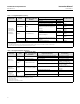
HEAT INSULATOR
REQUIRED
70
0 20 40 60 80 100 120 140 160
010 20
-20 -10
30 40 50 60
400
300
200
100
0
0
400
800
-325
AMBIENT TEMPERATURE (_C)
STANDARD TRANSMITTER
AMBIENT TEMPERATURE (_F)
HEAT INSULATOR
REQUIRED
TOO
HOT
NOTES:
FOR PROCESS TEMPERATURES BELOW -29_C (-20_F) AND ABOVE 204_C (400_F) SENSOR
MATERIALS MUST BE APPROPRIATE FOR THE PROCESS - SEE TABLE 1‐4.
2. IF AMBIENT DEW POINT IS ABOVE PROCESS TEMPERATURE, ICE FORMATION MIGHT CAUSE
INSTRUMENT MALFUNCTION AND REDUCE INSULATOR EFFECTIVENESS.
39A4070‐B
A5494‐1
425
80
-100
-200
176
-20-40
-40 -30
TOO
COLD
1
1
NO HEAT INSULATOR NECESSARY
Figure 2‐8. Guidelines for Use of Optional Heat Insulator Assembly
PROCESS TEMPERATURE (_F)
PROCESS TEMPERATURE (_C)
CAUTION
Measurement errors can occur if the torque tube assembly is bent or misaligned during installation.
1. When mounting a DLC3020f on a 249 sensor, secure the shaft extension to the sensor torque tube shaft via the
shaft coupling and set screws, with the coupling centered as shown in figure 2‐7.
2. Slide the access handle to the locked position to expose the access hole. Press on the back of the handle as shown in
figure 2‐2 then slide the handle toward the front of the unit. Be sure the locking handle drops into the detent.
3. Remove the hex nuts from the mounting studs.
4. Position the insulator on the digital level controller, sliding the insulator straight over the mounting studs.
5. Install 4 washers (key 78) over the studs. Install the four hex nuts and tighten.
6. Carefully slide the digital level controller with the attached insulator over the shaft coupling so that the access hole
is on the bottom of the digital level controller.
7. Secure the digital level controller and insulator to the torque tube arm with four cap screws.
8. Tighten the cap screws to 10 NSm (88.5 lbfSin).
Electrical Connections
The following describes how to make fieldbus connections to the digital level controller. For information on
connecting a simulate jumper, refer to page 19.
WARNING
To avoid personal injury resulting from electrical shock, do not exceed the maximum input voltage specified in table 1‐2 or
on the product nameplate. If the input voltage specified differs, do not exceed the lowest specified maximum input
voltage.