
Instruction Manual


Instruction Manual
D103434X012
Installation
November 2014
15
manual). Changing the mounting also changes the effective action, because the torque tube rotation for increasing
level, (looking at the protruding shaft), is clockwise when the unit is mounted to the right of the displacer and counter‐
clockwise when the unit is mounted to the left of the displacer.
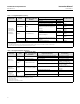
All 249 caged sensors have a rotatable head. That is, the digital level controller can be positioned at any of eight
alternate positions around the cage as indicated by the position numbers 1 through 8 in figure 2‐5. To rotate the head,
remove the head flange bolts and nuts and position the head as desired.
Figure 2‐5. Typical Mounting Positions for the FIELDVUE DLC3020f Digital Level Controller on a Fisher 249 Sensor
8
2
4
6
3
7
1
5
SENSOR
CAGED
CAGELESS
RIGHT‐OF‐DISPLACER
LEFT‐OF‐DISPLACER
1
1
1
NOT AVAILABLE FOR SIZE NPS 2 CL300 AND CL600 249C SENSOR.
8
2
4
6
1
3
7
5
249VS
249W
249W
249VS
Mounting the DLC3020f on a 249 Sensor
Refer to figure 2‐2 unless otherwise indicated.
1. If the set‐screw in the access handle, (see figure 2‐6) is driven against the spring plate, back it out until the head is
flush with the outer surface of the handle, using a 2 mm hex key. Slide the access handle to the open position to
lock the lever assembly in place and to expose the access hole. Press on the back of the handle as shown in figure
2‐2 then slide the handle toward the front of the unit. Be sure the locking handle drops into the detent.