
Instruction Manual


Instruction Manual
D103434X012
Installation
November 2014
13
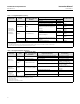
Figure 2‐2. Sensor Connection Compartment (Adapter Ring Removed for Clarity)
PRESS HERE TO
MOVE ACCESS HANDLE
SLIDE ACCESS HANDLE
TOWARD FRONT OF UNIT TO
EXPOSE ACCESS HOLE
ACCESS HOLE
MOUNTING STUDS
SHAFT CLAMP
SET SCREW
NOTE:
SET SCREW IS USED TO LOCK THE LEVER IN PLACE FOR OPERATION
1
1
Hazardous Area Classifications and Special Instructions for “Safe
Use” and Installation in Hazardous Locations
Refer to the DLC3020f Quick Start Guide (D103470X012) that ships with the instrument for Hazardous Area
Classifications and Special Instructions for “Safe Use” and Installations in Hazardous Locations. If a copy of this quick
start guide is needed contact your Emerson Process Management sales office or visit our website at www.Fisher.com.
Mounting
WARNING
To avoid personal injury or property damage, always wear protective gloves, clothing, and eyewear when performing any
installation operations.
Personal injury or property damage due to sudden release of pressure, contact with hazardous fluid, fire, or explosion can
be caused by puncturing, heating, or repairing a displacer that is retaining process pressure or fluid. This danger may not
be readily apparent when disassembling the sensor or removing the displacer. Before disassembling the sensor or
removing the displacer, observe the appropriate warnings provided in the sensor instruction manual.
Check with your process or safety engineer for any additional measures that must be taken to protect against process
media.
Mounting the 249 Sensor
The 249 sensor is mounted using one of two methods, depending on the specific type of sensor. If the sensor has a
caged displacer, it typically mounts on the side of the vessel as shown in figure 2‐3. If the sensor has a cageless
displacer, the sensor mounts on the side or top of the vessel as shown in figure 2‐4.